
Related Manuals for Fristam Pumps FDS Series


Summary of Contents for Fristam Pumps FDS Series
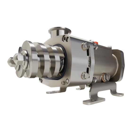
- Page 1 FDS Series Pumps Instruction and Maintenance Manual FDS Positive Displacement Pump (Original Instructions)
-
Page 2: Safety
The FDS series pump is available with any connection type desired and may be mounted with the inlet/ outlet connections in a horizontal or vertical orientation. The pump should be coupled to a motor/ drive assembly properly specified to give the desired performance for the required application. -
Page 3: Table Of Contents
FDS Series Pumps TABLE OF CONTENTS Safety ..........................2 Technical Information ......................4 Pump Operations ....................... 7 Spare Parts ..........................8 Transportation ........................8 Noise Reduction ........................8 Cleaning ..........................8 Installation ..........................9 Recommended Preventive Maintenance ................13 Drawing and Illustrations ....................14 Pump Assembly ......................14 Gearbox Assembly .......................14 Parts List ........................15... -
Page 4: Technical Information
FDS Series Pumps TECHNICAL INFORMATION SPECIFICATIONS Max. Flow Rate ....................88 GPM (FDS 1) .....................176 GPM (FDS 2) .....................440 GPM (FDS 3) .....................793 GPM (FDS 4) Max. Speed Range ....................3600 RPM Max. Viscosity....................1,000,000 cps Rotation ........................Reversible Mounting ................Horizontal (vertical optional) Max. - Page 5 FDS Series Pumps MAXIMUM PRESSURE Screw Size Max. Pressure: PSI (bar) 360 (25) 320 (22) 260 (18) 190 (13) 160 (11) 130 (9) 115 (8) 90 (6) MODELS 2-5 Max. Pressure: PSI (bar) 290 (20) 260 (18) 230 (16) 175 (12)
- Page 6 FDS Series Pumps SCREW PITCH SIZE FDS 1 FDS 2 FDS 3 FDS 4 FDS 5 15 mm 21 mm 26 mm 35 mm Pitch 1 .59” .83” 1.02” 1.38” 19 mm 26 mm 32 mm 44 mm Pitch 2 .75”...
-
Page 7: Pump Operations
FDS Series Pumps PUMP OPERATIONS INTENDED USE The standard FDS positive displacement pump versions are designed for use in hygienic applications. Each pump is specified according to customer specifications, including performance and materials of construction. The pump may only be used for the application it was specified for. -
Page 8: Spare Parts
Maintain good piping practices (see below). CLEANING SIP PROCESS FDS series pumps should only be used for SIP (Sterilization In Place) process with the prior approval of Fristam. Suitability may depend on selected elastomers and/or process temperatures. CIP PROCESS FDS series pumps are suitable for the CIP (Cleaning In Place) process. The following is a general ex- ample of the CIP process: •... -
Page 9: Installation
Failure to use an appropriate motor type may result in serious damage and/or injury. • When switching the pump mounting to vertical, please contact Fristam Pumps. PIPING CAUTION: Because the FDS pump is a highly efficient positive displacement pump, the user needs to ensure that the pump will not be over-pressurized during operation as this can cause severe damage to the pump. - Page 10 FDS Series Pumps • Avoid sump areas where sediment may FIGURE 3 collect (figure 3). • Use a check or “foot” valve on the inlet side of the pump in lift applications to keep the suction piping flooded. • Avoid throttling valves in the suction piping.
- Page 11 FDS Series Pumps ALIGNMENT In most cases, the pump will be shipped with a drive unit mounted on a baseplate. The drive and pump are aligned at the factory; however, this alignment should be checked after installation (Figure 7). Misalignment between the pump and drive can result in premature bearing failure or other damage.
- Page 12 A change in conditions (for example, higher viscosity product, higher differential pressure can overload the motor. For technical assistance regarding operating condition changes, please contact Fristam Pumps. Make sure that the pump is rotating in the correct direction. WATER FLUSH CONNECTIONS If your pump is equipped with a double mechanical product seal, water must be supplied to provide cooling and lubrication.
-
Page 13: Recommended Preventive Maintenance
FDS Series Pumps RECOMMENDED PREVENTIVE MAINTENANCE RECOMMENDED SEAL MAINTENANCE Visually inspect mechanical seal daily for leakage. Replace mechanical seal annually under normal duty. Replace mechanical seal as often as required under heavy duty. When replacing ANY seal part, it is important to replace ALL seal wear parts. -
Page 14: Drawing And Illustrations
FDS Series Pumps FDS PUMP HEAD ASSEMBLY FDS PUMP GEARBOX ASSEMBLY... -
Page 15: Parts List
FDS Series Pumps FDS PARTS LIST ITEM DESCRIPTION QTY. FDS 1 FDS 2 FDS 3 FDS 4 Gearbox 1310606100 1310606202 1310606300 1310606400 Gearbox Seal 1812000072 1812000036 1812000075 1812000077 Bearing, Front 1173001030 1173001028 1173001032 1173001034 Internal Retaining Ring 1148000042 1148000039 1148000045... -
Page 16: Single Mechanical Seal Assembly
FDS Series Pumps SINGLE MECHANICAL SEAL ASSEMBLY SINGLE MECHANICAL SEAL ASSEMBLY SINGLE MECHANICAL SEAL CROSS-SECTION 1265000711... -
Page 17: Double Mechanical Assembly
FDS Series Pumps DOUBLE MECHANICAL SEAL ASSEMBLY DOUBLE MECHANICAL SEAL ASSEMBLY DOUBLE MECHANICAL SEAL CROSS-SECTION 1265000712... -
Page 18: Maintenance Tools Required
FDS Series Pumps REQUIRED TOOLS FDS Tool List FDS1 FDS2 FDS3 FDS4 Pump Assembly Hex Head Bolt, Cover 17mm Socket 19mm Socket 24mm Socket 30mm Socket Hex Bolt, Housing/Casing 17mm Wrench 19mm Wrench 24mm Wrench 30mm Wrench SHCS, Housing 6mm Allen Socket... -
Page 19: Pump Disassembly
FDS Series Pumps PUMP DISASSEMBLY REMOVE THE COVER • Remove the cover bolts and washers. • Remove the cover from the casing. You may have to use a rubber mallet to gently tap the cover off the casing dowel pins. -
Page 20: Seal Replacement
FDS Series Pumps SEAL REPLACEMENT MECHANICAL SEAL REMOVAL • Loosen the four mechanical seal retainer bolts • Remove the mechanical seal retainers. • Remove the rotating units from the shafts. • Remove the stationary units from the housing. • Inspect as necessary. -
Page 21: Pump Assembly
FDS Series Pumps PUMP ASSEMBLY SCREW INSTALLATION • Casing must be removed from the gearbox. • Apply lubricant to the splines. • Install both screws simultaneously and ensure they are parallel in the front and back. NOTE: The screw with one dot should be assembled in the drive shaft and the screw with two dots should be installed on the idle shaft. - Page 22 FDS Series Pumps GAPPING THE PUMP • Remove the gearbox cover. • Using an Allen wrench, loosen the socket head cap screws on the idle gear retainer. • The idle shaft will be loose; allowing it to spin. The gap between the screws will change as you spin the idle shaft back and forth.
- Page 23 FDS Series Pumps INSTALL THE CASING • Install the casing/housing gasket onto the housing. • Install the casing onto dowel pins of the housing. • Tighten the casing/housing bolts. • Note taper location per your configuration INSTALL THE COVER •...
-
Page 24: Changing Screw Rotation Direction
FDS Series Pumps CHANGING SCREW ROTATION DIRECTION STANDARD (CONFIGURATION 1) • Inlet front, outlet top • Clockwise drive shaft rotation (view from the motor) • Casing taper located at the bottom Laser marking indicates location of casing taper [view from front, cover removed] REVERSE SCREW ROTATION (CONFIGURATION 2) •... -
Page 25: Changing Flow Direction
FDS Series Pumps CHANGING FLOW DIRECTION WARNING! Contact Fristam for pressures above 115 psi differential pressure. Modification to the shaft assembly is necessary. CONFIGURATION 3 • Inlet top, outlet front • Clockwise drive shaft rotation (view from the motor) •... -
Page 26: Pump Maintenance Record
FDS Series Pumps PUMP MAINTENANCE RECORD DATE SERVICED PERFORMED PERFORMED BY... - Page 27 FDS Series Pumps PUMP MAINTENANCE RECORD DATE SERVICED PERFORMED PERFORMED BY...
- Page 28 FDS Series Pumps PUMP MAINTENANCE RECORD DATE SERVICED PERFORMED PERFORMED BY...
- Page 29 FDS Series Pumps PUMP MAINTENANCE RECORD DATE SERVICED PERFORMED PERFORMED BY...
-
Page 30: Ec Declaration Of Conformity
FDS Series Pumps EC D EG D EClaration of onformity EClaration of nCorporation The manufacturer: Fristam Pumps The manufacturer: Fristam Pumps 2410 Parview Road 2410 Parview Road Middleton, WI 53562 Middleton, WI 53562 hereby declares that the following product (pump... -
Page 31: Warranty
All orders are subject to acceptance by Fristam Pumps USA Limited Partnership. Each Fristam Pumps item is warranted to be free from manufacturing defects for a period of one (1) year from the date of shipment, providing it has been used as recommended and in accordance with recognized piping practice, and providing it has not been worn out due to severe service, such as encountered under extremely corrosive or abrasive conditions. - Page 32 FDS Series Pumps 2410 Parview Road • Middleton, WI 53562-2524 © 2021 Fristam Pumps USA 1-800-841-5001 • 608-831-5001 Part #: 1050000303 Website: www.fristam.com/usa Drawing # 1250000039 Updated 11/17/2021 Email: fristam@fristampumps.com...
Need help?
Do you have a question about the FDS Series and is the answer not in the manual?
Questions and answers