Table of Contents
Advertisement
Quick Links
Original Instructions
Assembly Instructions
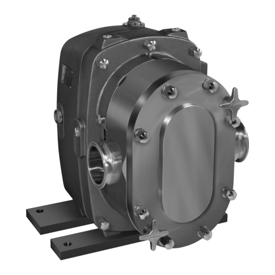
Positive Displacement Pump
FKL Series
Архангельск
(8182)63-90-72
Ижевск
Астана
(7172)727-132
Иркутск
Астрахань
(8512)99-46-04
Казань
Барнаул
(3852)73-04-60
Калининград
Белгород
(4722)40-23-64
Калуга
Брянск
(4832)59-03-52
Кемерово
Владивосток
(423)249-28-31
Киров
Волгоград
(844)278-03-48
Краснодар
Красноярск
Вологда
(8172)26-41-59
Курск
Воронеж
(473)204-51-73
Липецк
Екатеринбург
(343)384-55-89
Киргизия
Иваново
(4932)77-34-06
(3412)26-03-58
Магнитогорск
(395)279-98-46
Москва
(495)268-04-70
(843)206-01-48
Мурманск
(4012)72-03-81
Набережные Челны
(4842)92-23-67
Нижний Новгород
(3842)65-04-62
Новокузнецк
(8332)68-02-04
Новосибирск
(861)203-40-90
Омск
(3812)21-46-40
(391)204-63-61
Орел
(4862)44-53-42
(4712)77-13-04
Оренбург
(4742)52-20-81
Пенза
(8412)22-31-16
(996)312-96-26-47
Казахстан
https://fristam.nt-rt.ru/ || fmg@nt-rt.ru
(3519)55-03-13
Пермь
Ростов-на-Дону
(8152)59-64-93
Рязань
(8552)20-53-41
Самара
(831)429-08-12
Санкт-Петербург
(3843)20-46-81
Саратов
(383)227-86-73
Севастополь
Симферополь
Смоленск
(3532)37-68-04
Сочи
Ставрополь
(772)734-952-31
Таджикистан
(342)205-81-47
Сургут
(863)308-18-15
Тверь
(4912)46-61-64
Томск
(846)206-03-16
Тула
(812)309-46-40
Тюмень
(845)249-38-78
Ульяновск
(8692)22-31-93
Уфа
(3652)67-13-56
Хабаровск
(4812)29-41-54
Челябинск
(862)225-72-31
Череповец
(8652)20-65-13
Ярославль
(992)427-82-92-69
(3462)77-98-35
(4822)63-31-35
(3822)98-41-53
(4872)74-02-29
(3452)66-21-18
(8422)24-23-59
(347)229-48-12
(4212)92-98-04
(351)202-03-61
(8202)49-02-64
(4852)69-52-93
Advertisement
Table of Contents

Related Manuals for Fristam Pumps FKL Series


Summary of Contents for Fristam Pumps FKL Series
- Page 1 Original Instructions Assembly Instructions Positive Displacement Pump FKL Series Архангельск (8182)63-90-72 Ижевск (3412)26-03-58 Магнитогорск (3519)55-03-13 Пермь (342)205-81-47 Сургут (3462)77-98-35 Астана (7172)727-132 Иркутск (395)279-98-46 Москва (495)268-04-70 Ростов-на-Дону (863)308-18-15 Тверь (4822)63-31-35 Астрахань (8512)99-46-04 Казань (843)206-01-48 Мурманск (8152)59-64-93 Рязань (4912)46-61-64 Томск (3822)98-41-53 Барнаул...
-
Page 2: Table Of Contents
Table of Contents Introduction ............5 Pump Fixation ............11 Installation of Pipes ..........11 Foreword..............5 Electrical Connection ........... 12 Manufacturer............5 Connection of Sealing or Quenching Scope of Supply............5 Liquid (Optional)............ 12 Pump Without Motor (Optional) ...... 5 Cleaning.............. - Page 3 11.3 Troubleshooting Table ........24 11.4 Number Key ............. 26 11.5 EC Declaration of Conformity......28 11.6 EG- Einbauerklärung..........28 Appendix 2 – Assembly Instructions (Optional) ..............29 12.1 Safety Instructions..........29 12.2 Scope................29 12.3 Rating Plate .............. 29 12.4 Moving Without Motor........
-
Page 4: Introduction
1 Introduction – Attached documents – Order-Related Documents – Supplier documentation (motor, coupling, etc.) Foreword – Documentation on Fristam accessories (if applicable) This operator's manual describes all sizes, models, and versions of the FKL Pump Series. – Certificates (materials certificates, etc.), if applicable ... -
Page 5: Safety
/ / FKL PUMP SERIES / / / 2 Safety Maintain the pump pressure within the specified pressure range. (see chapter 11.1.2, "Maximum Discharge Pressures," page 23.) Basic Safety Instructions Impermissible Temperature Range Please read this operator's manual completely before using Personal injury and material damage from leakage or bursting of the pump and keep it available at the pump installation loca- pump. -
Page 6: Noise Emissions
Disposal 2.5.2 No Dry Running 2.7.1 Disposal of Transportation Package Recycle the transportation package. 2.7.2 Disposal of Grease Dispose of grease and objects saturated with grease in an Fig. 2 Safety label: "No Dry Running" environmentally friendly manner in accordance with applica- ble regulations. -
Page 7: Models
/ / FKL PUMP SERIES / / / Basic Versions 3.1.1 Pump With Synchromesh Gears (A) For all models, the following versions are available: – Single or double shaft seal Two seal types are available for use: single and double shaft seals. -
Page 8: Transportation
Moving With Industrial Truck Pump type Supplementary character 1 WARNING Pump size Unsecured Parts Supplementary character 2 Serious injuries, pinching of extremities, material damage. (17) Pump Type Before moving the pump secure it to prevent it from tipping Circumferential piston pump, self-priming over. -
Page 9: Storage
/ / FKL PUMP SERIES / / / 5 Storage WARNING Swinging Parts Pump Storage Conditions Crushing and serious injuries. Store the pump as follows: Start and stop the crane with pump smoothly. – Dry, in low humidity Ensure that the danger zone of the pump is clear of people. -
Page 10: Installation Location
Use a torque wrench or an impact driver with adjustable 6.4.2 Pump With Base Frame on Spherical Cap Bearings torque. (Optional) Set up the pump on the spherical cap bearings and align. Swinging During Adjustment of Spherical Cap Feet Material damage to system and pump. -
Page 11: Electrical Connection
/ / FKL PUMP SERIES / / / Cleaning Only use cleaning agents that comply with the hygiene guide- lines for the respective pumping medium. 1. Before sealing the pump ensure that there are no foreign ob- jects inside the pump or pipes. 2. -
Page 12: Monitoring Of Operation
Stopping of Operation If no pressure is noted in the "Sectional drawing of the shaft seal", the following applies: 1. Turn off the motor. – A max. pressure of 0.2 bar is allowed for seals to which 2. Close the valve in the suction line to prevent dry running of sealing fluid is applied without pressure or which are the pump. -
Page 13: Sip Process
/ / FKL PUMP SERIES / / / SIP Process Always wear gloves when performing maintenance-related work. NOTICE Uncontrolled Outflow of Liquids Dry Running of Pump With Vapor Personal injury and material damage from acid burns, poison- ing, or contamination. Damage to shaft seal. -
Page 14: Oil Level Check
10.4 Oil Level Check 7. Clean the bleed screw and the seals. 8. Install the screw plug and the bleed screw with the corre- The oil is checked on the oil level sight glass (23), which can be sponding seals. found on the side of the gearbox. - Page 15 / / FKL PUMP SERIES / / / – Outer Shaft Seal In this case, there are no shaft seal components in the groove on the rotor. Note: Only outer shaft seals are used for the FKL 600 model. Preparation 1.
-
Page 16: Mounting Of The Pump Casing
Fig. 19 Removal of shaft seal illustrating using the FKL100, single shaft seal 3. Carefully loosen the pump casing from the synchromesh gear using a plastic hammer and remove. Fig. 18 Exploded view of the FKL100, single shaft seal 4. Note: Loss of stationary bushing (38). Material damage. 3. - Page 17 / / FKL PUMP SERIES / / / If necessary, rework or replace pump parts. 10.9.3 Mounting of the Rotors Assemble carefully in clean conditions. The seals can easily be damaged. Replace all O-rings. To reduce friction, wet the O-rings and the sliding faces with water, alcohol, or silicone grease.
-
Page 18: Shaft Bearing Replacement
4. Loosen the coupling according to the coupling manufactur- Model Pump Size Thread Rotor Fastener er's specifications. Please see the attached supplier docu- Tightening Torque [Nm] mentation for the coupling. Rotor Nut Rotor Screw 5. Dispose of the old coupling parts in an environmentally M24 x 1.5 friendly manner. -
Page 19: Checking Of The Clearances
/ / FKL PUMP SERIES / / / 5. Detach the old gear motor from the base frame or the foun- Only for models FKL 100 and 200: Place O-rings and ec- dation. centric washer on the rotor screw. 6. - Page 20 Pump Size Axial clearances [mm] Standard High-Pressure High-Temper- ature Rotors Rotors (up to 15 bar) (15 bar and Rotors higher) FKL 50 0.06–0.08 0.06–0.08 0.11–0.13 FKL 100 0.10 0.15 0.20 FKL 200 0.10 0.15 0.22 FKL 600 0.25 Table 6 Axial clearances 4.
- Page 21 / / FKL PUMP SERIES / / / Fig. 26 Measuring radial clearance Model Radial clearance [mm] Standard High-pressure High-temper- rotor rotor ature (max. 15 bar) (from 15 bar) rotor FKL 50 0.05 – 0.07 0.09 – 0.12 0.15 – 0.18 FKL 100 0.10 –...
-
Page 22: Specifications
11 Appendix 1 11.1.2 Maximum Discharge Pressures Pump Size Maximum Discharge Pressure 11.1 Specifications [bar] FKL 50 FKL 100 11.1.1 Tightening Torques FKL 200 Tightening Torques for Screws and Nuts FKL 600 Material: Steel, Strength Class: 8.8 Table 8 Maximum discharge pressures Thread 11.1.3 Maximum Medium Temperatures Tightening Torque [Nm]... -
Page 23: Troubleshooting Table
/ / FKL PUMP SERIES / / / 11.3 Troubleshooting Table Problem Possible Cause Remedy Pump either does not pump or pumps irregu- Pump interior not completely filled with liquid; Fill pump interior with liquid; larly. pump interior not vented; discharge valve closed. open discharge valve. - Page 24 Problem Possible Cause Remedy Motor power consumption too high. Resistance in discharge line too high; pump Increase nominal size of discharge line; open throttled too much; flow rate too low. throttle valve; reduce speed using frequency con- verter on motor or control gear. Viscosity and/or density of pumping medium too Consult Fristam.
-
Page 25: Number Key
/ / FKL PUMP SERIES / / / 11.4 Number Key The general number key refers to the appended "Sectional drawings“. The part numbers conform to DIN 24250. Part Part Part Name Name Name Number Number Number Pump casing Mechanical seal spring Valve plate... - Page 26 Part Name Number Spring...
-
Page 27: Ec Declaration Of Conformity
/ / FKL PUMP SERIES / / / 11.5 EC Declaration of Conformity 11.6 EG- Einbauerklärung Der Hersteller: FRISTAM Pumpen KG (GmbH&Co.) Der Hersteller: FRISTAM Pumpen KG (GmbH&Co.) Kurt-A.-Körber-Chaussee 55 Kurt-A.-Körber-Chaussee 55 21033 Hamburg 21033 Hamburg erklärt hiermit, dass folgendes Produkt (Pumpe mit Motor): erklärt hiermit, dass es sich bei folgendem Produkt (Pumpe ohne Motor): –... -
Page 28: Appendix 2 - Assembly Instructions (Optional)
12 Appendix 2 – Assembly Instructions 12.4 Moving Without Motor (Optional) Transportation may only be performed by trained personnel. The pump can be moved using an industrial truck or a crane. 12.1 Safety Instructions Always move the pump in the installation condition. These assembly instructions are addressed solely to specialized employees. -
Page 29: Installation Location
/ / FKL PUMP SERIES / / / 12.4.3 Moving With Crane Do not lay the round sling over any sharp edges or cor- ners. WARNING Wrap the round sling around the casing and the drive shaft; see fig. 27, "Moving with round sling," page 28. Falling Parts 2. - Page 30 7. Fasten the coupling according to the coupling manufactur- er's specifications. 8. Install a noncontact, barrier-providing protective device (coupling guard) in accordance with Section 1.4, entitled "Re- quired Characteristics of Guards and Protective Devices," of the Machinery Directive 2006/42/EC. 9. The pump is now installed. Do not commission the pump unless the requirements of the EC Machinery Directive are met for the complete machine.
Need help?
Do you have a question about the FKL Series and is the answer not in the manual?
Questions and answers