Sign In
Upload
Download
Table of Contents
Contents
Add to my manuals
Delete from my manuals
Share
URL of this page:
HTML Link:
Bookmark this page
Add
Manual will be automatically added to "My Manuals"
Print this page
×
Bookmark added
×
Added to my manuals
Manuals
Brands
ARAG Manuals
Control Unit
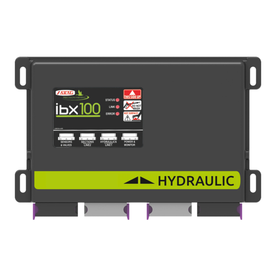
IBX100 4679005
Installation - use - maintenance
ARAG IBX100 4679005 Installation - Use - Maintenance
Ecu control unit
Hide thumbs
1
2
Table Of Contents
3
4
5
6
7
8
9
10
11
12
13
14
15
16
17
18
19
20
21
22
23
24
25
26
27
28
29
30
31
32
33
34
35
36
37
38
39
40
41
42
43
44
45
46
47
48
49
50
51
52
53
54
55
56
57
58
59
60
page
of
60
Go
/
60
Contents
Table of Contents
Troubleshooting
Bookmarks
Table of Contents
Table of Contents
1 Risks and Protections before Assembly
2 Intended Use
3 Precautions
4 Package Content
5 Position on Farming Machine
System Recommended Composition
Control Unit Fixing
Wiring Connections
6 Wiring Connections
General Precautions for a Correct Harness Position
Control Unit (ECU) Connection
Securing the Seletron Cables
Control Unit Valve Connection SYSTEM with SECTION VALVES
Hydraulic Valve Connection
Sensor Connection
7 ISOBUS System Cable Connection
In-Cab Cable Connection
ISOBUS Cable Connection
8 Introduction
OBJECT POOL" Loading
9 Setup
Tests and Checks before Programming
Command Location
10 Implement Settings > Basic Settings
11 Implement Settings > Advanced Setup
Boom
Flowmeters
Pressure Sensor
Valve Settings
Nozzle Data
Speed Settings
Rev Counter
Tank
Device Calibration
Press. Sensor Zero Value
Tank Level Zero Value
Tank Profile Calibration
Implement Geometry
System Configurations
Fence
Flowmeter Presets
12 Data and Settings
Manage Presets
Working Parameters
Info and Alarms
Implement Settings
Job Data
Sprayer Capability
System Status
Device Status
Isobus
Auxiliary Input Status
System Settings
Registration
Seletron Status
User Preferences
13 Seletron Connection
ID Reset
Seletron Replacement
Preliminary Operations
Replacement Procedure
14 Use
HOME" Main Screen
15 Job Functions
Output Temporary Increase and Decrease
Change Target Rate
Alarms
Automatic Functions
Application Rate Regulation
Test Speed
Nozzles Selection
Tank
Main Control and Section Management
Controls with Auxiliary Input
Controls WITHOUT Auxiliary Input
End Nozzles - for SYSTEMS with SELETRON, ONLY
16 Maintenance / Diagnostics / Repairs
Cleaning Rules
Key to LED Status
Error Messages
Troubleshooting
17 Technical Data
Power Supply
18 Disposal at the End of Service
19 Guarantee Terms
20 EU Conformity Declaration
Advertisement
Quick Links
Download this manual
IBX100 ECU CONTROL UNIT
4679004
4679005
Object Pool rel. 1.2.6
INSTALLATION, USE AND MAINTENANCE
Table of
Contents
Previous
Page
Next
Page
1
2
3
4
5
Advertisement
Table of Contents
Need help?
Do you have a question about the IBX100 4679005 and is the answer not in the manual?
Ask a question
Questions and answers
Related Manuals for ARAG IBX100 4679005
Control Unit ARAG IBX100 Installation, Use And Maintenance Manual
Electronic control unit (76 pages)
Control Unit ARAG ibx100 Directions For Installation, Use And Maintenance
Electronic control unit (56 pages)
Control Unit ARAG ibx100 Installation, Use And Maintenance Manual
Electronic control unit (42 pages)
Control Unit ARAG IBX100 Installation Manual
Rcu control unit (20 pages)
Control Unit ARAG IBX100 Installation, Use And Maintenance Manual
Electronic control unit (26 pages)
Control Unit ARAG IBX100 Installation - Use - Maintenance
Electronic control unit (78 pages)
Control Unit ARAG IBX100 4679004 Installation - Use - Maintenance
Ecu control unit (60 pages)
Control Unit ARAG 863 Series Installation, Use And Maintenance Manual
Electric control unit for crop-spraying applications (32 pages)
Control Unit ARAG 853 Series Installation, Use And Maintenance Manual
Electric ball valve with can-bus connection (51 pages)
Control Unit ARAG 463 Series Directions For Installation, Use And Maintenance
Manual control unit for crop-spraying applications (28 pages)
Control Unit ARAG 8537 Series Installation, Use And Maintenance Manual
Electric ball valve (21 pages)
Control Unit ARAG VISIO BLC Installation, Use And Maintenance Manual
Fixed geometry boom leveling kit (32 pages)
Control Unit ARAG 863T Series Installation, Use And Maintenance Manual
Boom section valves with fork coupling (20 pages)
Control Unit ARAG BRAVO 300S Quick Reference Manual
(2 pages)
Control Unit ARAG 453 Series Use And Maintenance
Electric ball valve (41 pages)
Summarization of Contents
INTRODUCTION
MANUAL USE MODES
Explains technical terms for installers, assuming end-user knowledge.
LIMITATIONS
Refers to general Virtual Terminal assembly; specific models are not mentioned unless installation is specific.
RESPONSIBILITY
Outlines installer's duties for proper installation and component compatibility.
1 RISKS AND PROTECTIONS BEFORE ASSEMBLY
2 INTENDED USE
3 PRECAUTIONS
4 PACKAGE CONTENT
5 POSITION ON FARMING MACHINE
5.1 System recommended composition
Guides on selecting correct connection cables based on system variants and nozzle count.
5.2 Control unit fixing
5.3 Wiring connections
6 WIRING CONNECTIONS
6.1 General precautions for a correct harness position
Guidelines for securing and routing cables to prevent damage and water infiltration.
6.2 Control unit (ECU) connection
Instructions for connecting the ECU, emphasizing ISOBUS connection timing and connector handling.
6.3 Securing the Seletron cables
6.4 Control unit valve connection - SYSTEM WITH SECTION VALVES
6.5 Hydraulic valve connection
6.6 Sensor connection
7 ISOBUS SYSTEM CABLE CONNECTION
7.1 In-cab cable connection
Instructions for connecting the in-cab cable, including ring nut tightening.
7.2 ISOBUS cable connection
Instructions for connecting the ISOBUS cable, ensuring proper connection and locking.
8 INTRODUCTION
8.1 "OBJECT POOL" loading
Explains how to display the OP selection page and load the ECU OP.
9 SETUP
9.1 Tests and checks before programming
Lists checks to perform before programming: component installation, power, and connections.
9.2 Command location
Explains the function of menu navigation buttons and confirmation actions.
10 IMPLEMENT SETTINGS > BASIC SETTINGS
Sprayer technology
Defines options for sprayer technology: electric-activated valves or Seletron valves.
Main valve type
Specifies options for the main control valve: None, 2-way, or 3-way.
Spraying spot type
Defines the type of Seletron units: single, twin, or fourfold.
Flowrate reference sensor
Explains the role of flowmeter and pressure sensor in calculating application rate.
Terminal nozzle type
Describes "Buffer zone" and "Fence" functions for enabling specific nozzle types.
Tank level source
Specifies the device used for reading tank level: manual, filling flowmeter, or level sensor.
11 IMPLEMENT SETTINGS > ADVANCED SETUP
Access to Implement Settings Menu
Shows how to navigate to the Implement Settings menu.
Implement Settings - Menu Structure
Outlines the structure of the Implement Settings menu, showing editable and non-editable items.
11.1 Boom
11.2 Flowmeters
11.3 Pressure sensor
11.4 Valve settings
11.5 Nozzle data
11.6 Speed settings
11.7 Rev counter
11.8 Tank
11.9 Device calibration
11.9.1 Press. sensor zero value
Procedure for zero calibration of the pressure sensor to ensure accurate readings.
11.9.2 Tank level zero value
11.9.3 Tank profile calibration
11.10 Implement geometry
11.11 System configurations
11.12 "Fence"
11.13 Flowmeter presets
12 DATA AND SETTINGS
12.1 Manage presets
Allows setting and activating up to 20 different treatment configurations (Presets).
12.2 Working parameters
12.3 Info and alarms
12.4 Implement settings
12.5 Job data
12.6 Sprayer capability
12.7 System status
12.7.1 Device status
Displays detailed system information, including sensor signals, power consumption, and versions.
12.7.2 ISOBUS
12.7.3 Auxiliary input status
12.7.4 System settings
12.7.5 Registration
12.7.6 Seletron status
12.8 User preferences
13 SELETRON CONNECTION
Seletron status
Displays Seletron status and connection diagnostics, with color legend for operation status.
Connection sequence for single and twin Seletron devices
Step-by-step guide for connecting single and twin Seletron devices sequentially.
Connection sequence for fourfold Seletron devices
Step-by-step guide for connecting fourfold Seletron devices sequentially.
NOZZLES FOR "Buffer zone"
Instructions on connecting Seletron units for "Buffer zone" applications.
"Fence" NOZZLES
Instructions on connecting Seletron units for "Fence" nozzle applications.
13.1 ID Reset
13.2 SELETRON REPLACEMENT
13.2.1 Preliminary Operations
Prepares the system for Seletron replacement, ensuring safety and activating specific settings.
13.2.2 Replacement procedure
Procedure for replacing Seletron devices, including disconnection of incorrectly paired units.
14 USE
14.1 "HOME" main screen
Overview of the "HOME" main screen, its buttons, and displayed items.
15 JOB FUNCTIONS
15.1 Output temporary increase and decrease - Change target rate
How to change the spray rate value for the job on the "Home" screen.
15.2 Alarms
Displays a summary of active alarm notifications for operators.
15.3 Automatic functions
15.3.1 Application rate regulation
Enables/disables automatic output adjustment based on speed and boom status.
15.3.2 Test speed
Allows enabling/disabling speed simulation for regulation tests with a stopped machine.
15.3.3 Nozzles selection
15.4 Tank
15.5 Main control and section management
15.5.1 Controls WITH Auxiliary Input
Refers to user manual for controls with Auxiliary Input.
15.5.2 Controls WITHOUT Auxiliary Input
Explains how valves are controlled directly via the monitor touch-screen panel without Auxiliary Input.
15.6 End nozzles - FOR SYSTEMS WITH SELETRON, ONLY
16 MAINTENANCE / DIAGNOSTICS / REPAIRS
16.1 Cleaning rules
Guidelines for cleaning the control unit using a soft cloth and avoiding direct water jets.
16.2 Key to LED status
Explains the meaning of LED colors (green, yellow, red) and their flashing patterns for status indication.
16.3 Error messages
16.4 Troubleshooting
17 TECHNICAL DATA
18 DISPOSAL AT THE END OF SERVICE
19 GUARANTEE TERMS
20 EU CONFORMITY DECLARATION
Table of Contents
Print
Rename the bookmark
Delete bookmark?
Delete from my manuals?
Login
Sign In
OR
Sign in with Facebook
Sign in with Google
Upload manual
Upload from disk
Upload from URL
Need help?
Do you have a question about the IBX100 4679005 and is the answer not in the manual?
Questions and answers