ARAG ibx100 Installation, Use And Maintenance Manual
Electronic control unit
Hide thumbs
Also See for ibx100:
- Installation - use - maintenance (78 pages) ,
- Installation, use and maintenance manual (76 pages) ,
- Directions for installation, use and maintenance (56 pages)

Subscribe to Our Youtube Channel
Related Manuals for ARAG ibx100


Summary of Contents for ARAG ibx100
- Page 1 IBX100 ELECTRONIC CONTROL UNIT 4679002 Object Pool rel. 1.2.0 INSTALLATION, USE AND MAINTENANCE...
- Page 2 This manual is an integral part of the equipment to which it refers and must accompany the equipment in case of sale or change of ownership. Keep it for any future reference; ARAG reserves the right to modify product specifications and instructions at any moment and without notice.
-
Page 3: Table Of Contents
CONTENTS Risks and protections before assembly .........4 19 user preferences ..............30 Intended use ................4 20 USE ..................31 20.1 Alarms ................31 Precautions ................4 21 Auto..................32 Package content ...............4 21.1 Rate ................32 Position on farming machine ..........5 21.2 Spinner speed ..............33 System recommended composition .........5 21.3 Speed simulation ............33 Control unit fixing .............6... -
Page 4: Risks And Protections Before Assembly
• RESPONSIBILITY The installer must carry out "workmanlike" installations and ensure to the end user the perfect operation of the whole system both with ARAG components only and other brands' components. ARAG always recommends using its components to install control systems. -
Page 5: Position On Farming Machine
INSTALLATION POSITION ON FARMING MACHINE System recommended composition WARNING: DO NOT CONNECT ISOBUS CONNECTOR ( chap. 7 on page 9 THIS CONNECTION MUST BE CARRIED OUT LATER, ONLY AFTER INSTALLING ALL THE COMPONENTS. To connect all parts of the system correctly, make sure to use the proper connection cables. Consider any variants depending on system type. -
Page 6: Control Unit Fixing
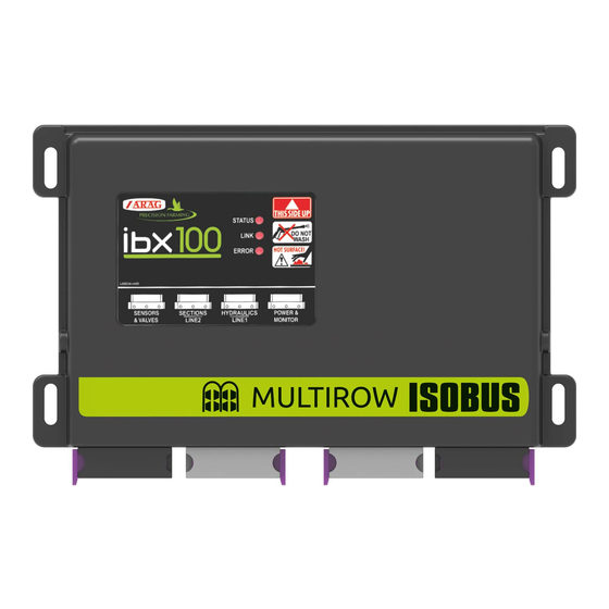
INSTALLATION Control unit fixing Fix the control unit in a visible position within easy reach as shown in the figure. IBX100 Fig. 3 Consider all necessary connections of the device (par. ), the cable length, and make sure there is enough "Wiring harness connection"... -
Page 7: Wiring Connections
• Use of unsuitable cables not provided by ARAG automatically voids the warranty. • ARAG is not liable for any damage to the equipment, persons or animals caused by failure to observe the above instructions. General precautions for a correct harness position •... -
Page 8: Connection Of Proportional Hydraulic Valves
• inductive speed sensor (code 467100.086); • magnetic speed sensor (code 467100.100). All ARAG sensors use the same type of connector. Connect the sensor connector to the relevant harness; make sure it is correctly fitted and push it until locking it. -
Page 9: Isobus System Cable Connection
Use the cable supplied in the auxiliary input package: ARAG Auxiliary Input control system is not compulsory on all systems, and must thus be ordered separately. Some Virtual Terminals allow controlling spreading spinners and gate directly from monitor touch-screen panel. -
Page 10: Object Pool Loading
OBJECT POOL LOADING “OBJECT POOL” LOADING Images and the relevant description texts contained in this manual are given as a reference as they can vary depending on the Virtual Terminal used. If the descriptions do not correspond to the text displayed in your Virtual Terminal, refer to the manual attached to the latter. -
Page 11: Control Layout
USING THE KEYS CONTROL LAYOUT Goes back to main screen Goes back to previous menu, or scrolls the pages of a menu (previous page) Scrolls the pages of a menu (next page) Saves the changes to current page Fig. 14 Quits without confirming the changes Saves the changes Fig. -
Page 12: Home
HOME HOME MENU SELECTION BUTTONS Data and Settings Alarms AUTO Tank Change target Main control ON/OFF Fig. 18 DATA AND SETTINGS Data and Settings Data and Settings Allows setting all the items. Fig. 19 Before settting Data and Settings check: •... -
Page 13: Implement Settings
IMPLEMENT SETTINGS IMPLEMENT SETTINGS Fig. 20 Configure farming machine settings. 1 - 2 Fig. 21 Basic settings 12.1 Allows configuring: 1 / 3 Belt actuator : type of device used to control spreading belts. Motorized valve : system with electric-activated valves - with gearmotor. PWM valve : system with solenoid valves. -
Page 14: Tank
IMPLEMENT SETTINGS 12.2 Tank Allows setting the tank data: 1 / 1 Tank settings Reserve : indicate the reserve value under which the alarm is triggered : indicate the tank capacity. Capacity 12.3 Belt Allows setting the spreading belt data: 1 / 3 Belt settings Sensor constant... -
Page 15: Speed
Spinner actuator Motorized valve PWM valve 2 / 3 Auxiliary commands : select the type of auxiliary control (Auxiliary Input) connected to the system. • ARAG Direct Switches • ARAG joystick • User Direct Switches • User joystick Auxiliary enable... -
Page 16: Calibration
IMPLEMENT SETTINGS 12.7 Calibration Allows setting the calibration data: 1 / 1 Calibration settings Mode : selects the type of control to carry out calibration. • : during calibration the system tries to keep the speed target set constant. Belt speed control •... -
Page 17: Manage Presets
MANAGE PRESETS MANAGE PRESETS This menu allows: - Setting 8 different treatment configurations: Preset - Activating one configuration among the preset ones. - Consult job data of the treatment selected: Preset Fig. 26 Number Name Rate of job of job Allows selecting and activating the Presets and setting them. -
Page 18: Calibration Parameters
MANAGE PRESETS 13.1 Calibration parameters Features of the selected Preset Activates or deactivates value entry. Density THE VALUE Enter the product density value suitable for calibration start moment. COULD BE DIFFERENT FROM THE NOMINAL VALUE Enter the value. Calibration factor Allows selecting if the current must be... -
Page 19: Weight Comparison
MANAGE PRESETS 13.1.2 Weight comparison WARNING: before starting the procedure, make sure that the spreading system is off (position OFF). The spreading belt and spinners must NOT be in motion. - Insert the material in the tank. - Activate the spreading system. WARNING: The material starts flowing out. -
Page 20: Calibration Procedure
MANAGE PRESETS 13.1.3 Calibration procedure WARNING: before starting the procedure, make sure that the spreading system is off (position OFF). The spreading belt and spinners must NOT be in motion. - Insert the material in the tank. - Check that the simulated speed is enabled and select the type of control to carry out the calibration ( “12.7 Calibration"... - Page 21 MANAGE PRESETS Confirm. Fig. 36 Enter the actual value of product quantity flown out of the tank. Confirm. Fig. 37 Save calibration. Fig. 38...
-
Page 22: Preset Totals - Preset Averages
MANAGE PRESETS Preset totals - Preset averages 13.2 Allows displaying and deleting data of the selected. Preset - Select the Preset - Use the keys to scroll the pages Fig. 39 - Use the key to delete job data; WARNING: total counters and average values are simultaneously deleted. -
Page 23: Working Parameters
WORKING PARAMETERS WORKING PARAMETERS Allows setting the farming machine job limits. Fig. 41 Activate the vehicle minimum speed to configure this menu. Set the minimum job speed: the system blocks the spreading when the tractor speed is lower than the set speed. Set the increase / decrease amount for the output value: the set value increases / decreases when the keys are pressed. -
Page 24: Alarms
ALARMS ALARMS This menu allows setting visual and acoustic alarm warnings. Alarm activated / Alarm deactivated. For the procedure to be followed when an alarm occurs, please refer to par. “25.3 Error messages" on page 39 Fig. 43 Alarm enabled when the rate is different from the preset one ( 14 on page 23 Alarm enabled when the spreading belt speed exceeds the preset limits ( 12.3 on... -
Page 25: Job Data
JOB DATA JOB DATA Allows consulting treatment total data. Fig. 47 Resets job data. Fig. 48... -
Page 26: Capacity
CAPACITY CAPACITY Allows checking treatment performance based on speed and configurations installed on the machine. Fig. 49 Fig. 50 Press 1 and 2 to increase or decrease the simulated speed: the system simulates the minimum and maximum rate. 3 enter the simulated rate value: the system simulates the minimum and maximum speed. -
Page 27: Status
STATUS STATUS Allows checking the correct operation of the system. Fig. 52 1 Press Restart ECU button to restart ECU and confirm the control unit restart. Fig. 53 18.1 Device status Displays system information: Hardware working correctly Hardware malfunction Fig. 54... -
Page 28: Isobus
STATUS 18.2 ISOBUS Displays information on ISOBUS protocol. 1 Allows displaying the OP on another system, if any, present on the ISOBUS line. 2 Allows deleting and reloading the ECU OP. 3 Allows reloading the TC. Fig. 55 18.2.1 Auxiliary commands Checks the connection of the Auxiliary Input. -
Page 29: Test Controllers
STATUS Test controllers 18.3 This menu allows checking the correct operation of the spreading belt and spinners: Before carrying out the test, make sure that the output is enabled. 1-2 These buttons allow starting the operation test of the spreading belt and spinners. 3-4 These buttons allow interrupting the operation test of the spreading belt and spinners. -
Page 30: User Preferences
: allows configuring both the machine features and the Technician treatment: an access PIN can be set. • : for ARAG staff, only. ARAG-Tech Fig. 61 Set the full scale for speed displayed in HOME job screen. Set the full scale of spreading belt displayed in HOME job screen. -
Page 31: Use
DISPLAY ITEMS Output variation: Instant output Every symbol corresponds to a Target rate Increase Auxiliary Input Automatic management of spreading spinners ON/OFF Decrease ON/OFF Automatic rate adjustment ON/OFF Enabled alarm Check of ON / OFF job counters Automatic output management ON/OFF variable application Speed Spreading belt RPM... -
Page 32: Auto
AUTO Auto Allows setting the manual or automatic mode: - rate control. - spreading spinner control. Allows enabling or disabling the simulated speed. Fig. 66 For the procedure to be followed when an alarm occurs, please refer to par. 25.3 Fig. -
Page 33: Spinner Speed
21.2 Spinner speed “HOME” SCREEN Start-up AUTOMATIC Automatic management of spreading spinners. Fig. 69 “HOME” SCREEN Start-up MANUAL Manual management of spreading spinners. Fig. 70 21.3 Speed simulation “HOME” SCREEN Allows enabling/disabling the speed simulation. Simulation speed modification: with active simulation press the indicated keys Increase Decrease Fig. -
Page 34: Tank
TANK Manages tank filling. Tank Fig. 72 Reset of tank content Range Filled quantity manual setup Manual setting of tank content Tank filling Tank level Fig. 73 22.1 Reset of tank content 1 - 2 Press to change the tank content to zero. -
Page 35: Filled Quantity Manual Setup
22.2 Filled quantity manual setup 1 Press to set the quantity of product filled in the tank. 2 - 3 Set the value and confirm. The display shows the quantity of product contained in the tank. It is not possible to set values higher than tank total capacity. -
Page 36: Change Target
CHANGE TARGET This menu allows making a temporary change in rate and RPM of spreading spinners: Change target Fig. 78 “HOME” SCREEN “HOME” SCREEN Increases the value at consecutive intervals. Decreases the value at consecutive intervals. Resets the value set in the enabled. -
Page 37: Main Control On/ Off
Controls WITH Auxiliary Input efer to the user's manual supplied with the device. ARAG Auxiliary Input control system is not compulsory on all systems, and must thus be ordered separately. Auxiliary Input ON Some systems allow controlling section valves directly from monitor touch-screen panel. -
Page 38: Maintenance / Diagnostics / Repairs
MAINTENANCE / DIAGNOSTICS / REPAIRS MAINTENANCE / DIAGNOSTICS / REPAIRS 25.1 Cleaning rules - Clean only with a soft wet cloth. - DO NOT use aggressive detergents or products. - DO NOT aim water jets directly at control unit. Fig. 83 25.2 LED status key COLOR... -
Page 39: Error Messages
SOLUTION MODE A control unit component or part is Replace the control unit damaged Internal control unit IBX100 hardware fault! error Check sensor status and electrical Sensor signals are not valid connection. Spinners move when Check the cause of spinner movement and... -
Page 40: Troubleshooting
MAINTENANCE / DIAGNOSTICS / REPAIRS 25.4 Troubleshooting MALFUNCTION CAUSE SOLUTION Control valve is not connected Connect the control valve Check that the part of harness, connectors and Harness damaged cables, related to valve connection to the control unit is not damaged Spinner speed does not reach the desired value Check the set limit correctness, and correct it if Speed maximum or minimum limit reached... -
Page 41: Technical Data
Dispose of the system in compliance with the established legislation in the country of use. GUARANTEE TERMS 1. ARAG s.r.l. guarantees this apparatus for a period of 360 days (1 year) from the date of sale to the client user (date of the goods delivery note). - Page 42 Only use genuine ARAG accessories or spare parts to make sure manufacturer guaranteed safety conditions are maintained in time. Always refer to the internet address www.aragnet.com 42048 RUBIERA (Reggio Emilia) - ITALY Via Palladio, 5/A Tel. +39 0522 622011 Fax +39 0522 628944 http://www.aragnet.com...
Need help?
Do you have a question about the ibx100 and is the answer not in the manual?
Questions and answers