
Related Manuals for ARAG VISIO BLC


Summary of Contents for ARAG VISIO BLC
- Page 1 FIXED GEOMETRY BOOM LEVELING KIT 4670612 Software rel. 2.1.X INSTALLATION, USE AND MAINTENANCE...
-
Page 2: Table Of Contents
This manual is an integral part of the equipment to which it refers and must accompany the equipment in case of sale or change of ownership. Keep it for any future reference; ARAG reserves the right to modify product specifications and instructions at any moment and without notice. -
Page 3: Risks And Protections
• RESPONSIBILITY The installer must carry out "workmanlike" installations and ensure to the end user the perfect operation of the whole system both with ARAG components only and other brands' components. ARAG always recommends using its components to install control systems. -
Page 4: Package Content
INSTALLATION PACKAGE CONTENT 1 Visio BLC 2 IBX100 hydraulic control unit 3 Ultrasonic sensors (no. 2) 4 Connection cables (ref. par. 6.1 System typical composition • Extension for sensors - 5 m (no. 2) • Adapter cables for ultrasonic sensors (no. 2) •... -
Page 5: Visio Blc
INSTALLATION VISIO BLC Fig. 3 Fig. 4 Set mounting rail in cabin and fasten it with the relevant screws ( ), in a position where VISIO can be easily seen and at hands' reach, but Fig. 4 away from any moving organs. -
Page 6: Installation Of Ultrasonic Sensors
INSTALLATION INSTALLATION OF ULTRASONIC SENSORS It is the installer responsibility to check that all indications described are complied with. The images relevant to sensors are purely indicative. Precautions to follow for a long-lasting installation: • Fix the sensor to a strong structure. •... -
Page 7: Sensor Correct Identification And Positioning
INSTALLATION Sensor correct identification and positioning Two types of layouts are available: • BASIC SETUP - with a pair of sensors Fig. 9 Fig. 9 Place the sensors in relation to the boom center = external pair of sensors (far from boom center), at a distance from boom end corresponding (LH side) + (RH side) approximately to 30% of the half-boom length. -
Page 8: Sensor Optimal Orientation
INSTALLATION Sensor optimal orientation • Lateral inclination (internal) The sensors must be oriented towards the nearest side of the tractor; an inclination of 5° is recommended and useful to compensate the gradient of the boom due to the BLC system correction. Fig. -
Page 9: Wiring Connections
• Use of unsuitable cables not provided by ARAG automatically voids the warranty. • ARAG is not liable for any damage to the equipment, persons or animals caused by failure to observe the above instructions. General precautions for a correct harness position •... -
Page 10: Wiring Harness Connection
Hydraulic unit to the corresponding socket on the remote control unit. Visio BLC / Power supply Visio BLC / IBX100 hydraulic unit connection REF. CABLE 4 VISIO IBX100 par. 6.1 REF. CABLE 3 par. 6.1... -
Page 11: Accessories
INSTALLATION ACCESSORIES Pendrive The pendrive may be used to exchange data with the BLC VISIO and IBX100. Before use, format the SD board in FAT 32 mode; make sure that the board is not protected and can be read by the system. Most pendrives with up to 2 Gb memory are compatible. -
Page 12: Setting
SETTING SETTING 10.1 Tests and checks before setting Before setup, check: • that all components are correctly installed; • the correct connection to the power source; • the component connection. Failure to correctly connect system components or to use specified components might damage the device or its components. 10.2 Controls in the menu SWITCHING ON... -
Page 13: Menu Structure
SETTING MENU STRUCTURE For a correct use of the keys during setting, refer to par. 10.2 Start procedure Number of sensors External sens. [X] Basic settings External sens. [Y] Internal sens. [X] Internal sens. [Y] HL Button Boom geometry BLC settings Boom settings Actuators Boom width... -
Page 14: Setup Menu
SETTING SETUP MENU From the main page, press keys at the same time for 2 seconds to access. Fig. 24 12.1 BLC settings This menu allows entering the mechanical characteristics of the spraying boom and the headland detection mode. Setup menu Access the Setup menu BLC settings... -
Page 15: Basic Settings - Wizard
SETTING 12.1.1 Basic settings - WIZARD Access the menu. BLC settings Press to access the Basic settings BLC settings Basic settings menu. Basic settings Start procedure... Press to start the wizard. Status: OK! VISIO will guide you during the Boom settings Number of sensors configuration: follow the steps and select Parameters adjust. - Page 16 SETTING SYSTEM WITH 4 SENSORS Fig. 30 • ). Number of ultrasonic sensors used by the BLC control. Number of sensors • : value relating to (pair of external sensors). External sens. [X] BOOM BOOM ULTRASONIC ULTRASONIC CENTER CENTER SENSOR SENSOR Horizontal distance between the longitudinal axis of EXTERNAL sensors and boom center ( Fig.
-
Page 17: Boom Settings
SETTING 12.1.2 Boom settings Access the BLC settings > Boom settings menu. Boom settings Boom geometry 12.2.7 To modify these settings, see Operating mode . par. Fixed The display will show the current setting below the selected item. Actuators Use of the keys at the bottom of the page. Boom width Fig. - Page 18 SETTING 12.1.3 Adjustment parameters > > > The values must be detected directly on the machine because strictly linked to the factory model. DURING MEASURING PROCEDURES, MOVE THE BOOM ALONG THE MAXIMUM ALLOWABLE DISTANCE, COMPATIBLY WITH THE MACHINE MECHANICAL CHARACTERISTICS AND DIMENSIONS. Height ctrl aggr.
- Page 19 SETTING 12.1.3 Adjustment parameters > > > The values must be detected directly on the machine because strictly linked to the factory model. DURING MEASURING PROCEDURES, MOVE THE BOOM ALONG THE MAXIMUM ALLOWABLE DISTANCE, COMPATIBLY WITH THE MACHINE MECHANICAL CHARACTERISTICS AND DIMENSIONS. Gain height error - PROPORTIONAL GAIN ON BOOM HEIGHT CONTROL Height error gain This parameter works in combination with the aggressiveness of the boom height control.
-
Page 20: Funct. Definition
IBX Properties IBX Properties Press the key on the side to scroll the items. Device name Hydraulic Arag The display will show the current setting below the selected item. Hardware version Use of the keys at the bottom of the page. -
Page 21: Options
SETTING 12.2 Options Access the > Setup menu Options Setup menu Options Press to edit the selected menu item. BLC settings Language Options English The display will show the current setting Unit of measurement below the selected item. Setup management Display contrast Use of the keys at the bottom of the page. -
Page 22: User Access
Manager ARAGTech : maximum access level; access to all control parameters. Technician : for ARAG staff only (assistance). It requires an access PIN number. Fig. 50 ARAGTech ENTERING THE PIN NUMBER ONLY Manager and Technician users can set an access PIN number, as follows: User access Select the access mode to enter the PIN number. -
Page 23: Setup Management
12.3 Setup management The VISIO BLC settings can be loaded or saved on USB* pendrive so as to reconfigure the device if necessary, solve problems or configure another VISIO BLC without repeating all operations manually. Once installation is completed, and you have checked VISIO BLC correct operation, we recommend storing the whole configuration onto USB pendrive. -
Page 24: Test
SETTING 12.4 Test This menu allows user to view some data and carry out an operation test of VISIO. Access the > Setup menu Test Setup menu Test Press the key on the side to scroll the items. Options Firmware version The display will show the current setting Setup management 2.1.0... -
Page 25: Ibx100 Hydraulic Update
Factory default It resets the selected device factory settings (BLC VISIO or IBX100).The use of the keys is explained at the bottom of the page. 12.6.1 VISIO restore The VISIO BLC settings are reset - from par. to par. 12.2.1 12.2.7... -
Page 26: Preliminary Setup For Use
SETTING PRELIMINARY SETUP FOR USE 13.1 Quick settings menu From the main screen, press for two seconds to access the Quick settings Fig. 71 Access the menu. Quick settings Quick settings Spraying height Press to edit the selected menu item. 0.50 m The display will show the current setting below the selected item. -
Page 27: Blc Control - How It Works
JOB FUNCTIONS BLC CONTROL - HOW IT WORKS 14.1 Fixed geometry The BLC control considers the boom as a single body: it is then a fixed geometry control as the division at boom section is negligible. The boom must be COMPLETELY open. To the keep the boom in the desired position, the BLC control performs two types of independent corrections at the same time: •... -
Page 28: Use
JOB FUNCTIONS 15.1 Start-up Before starting the BLC system, set the working and headland heights, described in par. 13.1 Quick settings on page 26 - To activate the BLC control, set the control mode to AUTOMATIC - To deactivate the BLC control, set the control mode to MANUAL 15.2 AUTOMATIC and MANUAL mode ... -
Page 29: Automatic Control A
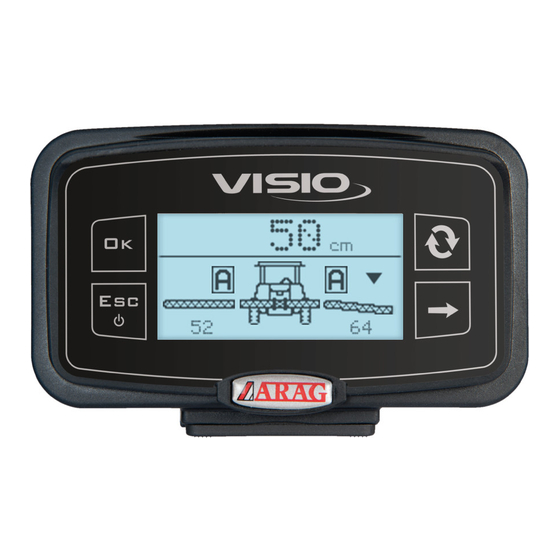
JOB FUNCTIONS 15.3 Automatic control In this mode, the BLC control AUTOMATICALLY ACTIVATES the hydraulic valves duly adjusting the height and tilting of the spraying boom. During spraying, boom positioning (estimated) is displayed on the monitor. When the BLC system works in automatic mode, the IBX100 hydraulic unit: ... -
Page 30: Maintenance / Diagnostics / Repairs
MAINTENANCE / DIAGNOSTICS / REPAIRS MAINTENANCE / DIAGNOSTICS / REPAIRS • Clean only with a soft wet cloth. • Do not use aggressive detergents or products. • Do not clean equipment with direct water jets. 16.1 Error messages the control automatically switches to MANUAL mode In case of error, the BLC system is deactivated: Solve the problem, then reactivate the AUTOMATIC mode (par. -
Page 31: Technical Data
GUARANTEE TERMS 1. ARAG s.r.l. guarantees this apparatus for a period of 360 days (1 year) from the date of sale to the client user (date of the goods delivery note). The components of the apparatus, that in the unappealable opinion of ARAG are faulty due to an original defect in the material or production process, will be repaired or replaced free of charge at the nearest Assistance Center operating at the moment the request for intervention is made. - Page 32 Only use genuine ARAG accessories or spare parts to make sure manufacturer guaranteed safety conditions are maintained in time. Always refer to the Internet address www.aragnet.com 42048 RUBIERA (Reggio Emilia) - ITALY Via Palladio, 5/A Tel. +39 0522 622011 Fax +39 0522 628944 http://www.aragnet.com...
Need help?
Do you have a question about the VISIO BLC and is the answer not in the manual?
Questions and answers