
Subscribe to Our Youtube Channel
Related Manuals for ARAG 463 Series


Summary of Contents for ARAG 463 Series
- Page 1 MANUAL CONTROL UNIT FOR CROP-SPRAYING APPLICATIONS 463 - 464 - 465 - 471 SERIES INSTALLATION, USE AND MAINTENANCE...
-
Page 2: Table Of Contents
This manual is an integral part of the equipment to which it refers and must accompany the equipment in case of sale or change of ownership. Keep it for future reference; ARAG reserves the right to modify the specifications and instructions regarding the product at any time and without prior notice. -
Page 3: Product Description
ARAG is not liable for any damage caused directly or indirectly by the type of fluids used for spraying by its control units. -
Page 4: Functioning Of The Product
FUNCTIONING OF THE PRODUCT Composition of the manual control units The pictures of the control units in the following pages must be considered a mere example and might not correspond to the configuration of your own unit. 2.1.1 Manual control units with 471 SERIES main control valve Fig. -
Page 5: Manual Control Units With 464 Series Main Control Valve
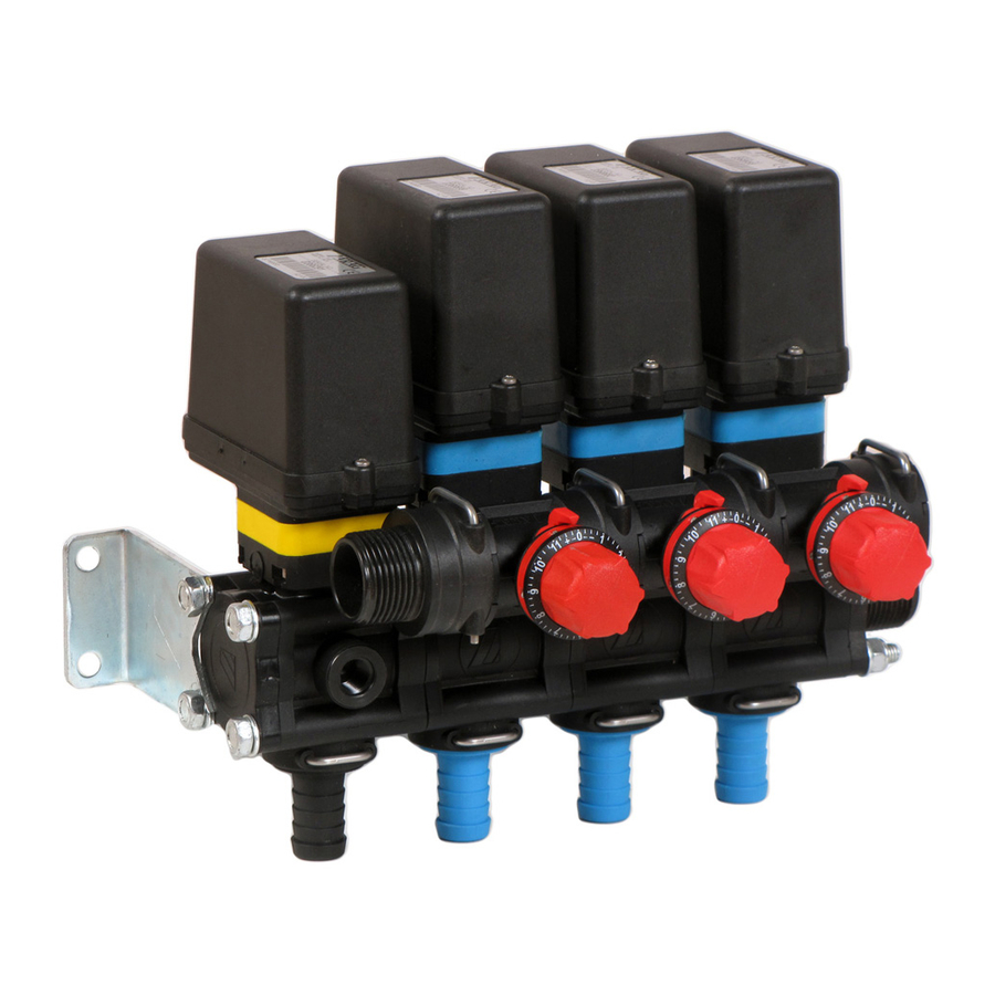
2.1.2 Manual control units with 464 SERIES main control valve Fig. 2 1 Main control lever 2 Maximum pressure valve 3 Proportional valve 4 Filter 5 Boom section valves 6 Adjustable compensation cocks (calibrated backflows) 7 Pressure gauge adapter IN Intake of liquid for spraying OUT A Discharge for maximum pressure valve OUT B Discharge for calibrated backflows OUT C Discharge for proportional valve... -
Page 6: Functions Of Components
Functions of components Main control lever Controls the direction of the liquid through the system. Lever down = liquid sent directly to the circuit for application Lever up = liquid sent to the tank; the suction system, if present, starts functioning. Maximum pressure valve Eliminates the excess liquid when the set pressure level is reached. -
Page 7: Installation
Contact skilled personnel for any intervention requiring modifications to the configu- ration of the hydraulic connections. ARAG is not liable for any damage to equipment or injury to persons, animals or things caused by incorrect or unsuitable connection of the unit. -
Page 8: Installing And Connecting The Unit
Installing and connecting the unit Install the control unit and secure it using the appropriate holes located on the brackets, as shown in Fig. 3. Fixing holes Fig. 3 We recommend following the standard array for assembly for optimum performance of the unit, as shown in Fig. -
Page 9: Connecting Up The System
Connecting up the system Connect the hoses in the system according to the layout shown below. Take care: - Not to connect backflow hoses in the lower part of the tank with the intention of using them as hydraulic stirrers; only place them in the upper part so the liquid drops down by gravity, as shown in Fig. - Page 10 - Make a separate connection of the backflow of the valves with the tank, as shown in Fig. 7. RIGHT CORRETTO Fig. 7 WRONG ERRATO Fig. 8...
-
Page 11: Settings Before Use
Fit the pressure gauge on the adap- ter, screw it down completely without tightening it excessively. Use ARAG pressure gauges with 1/4" M coupling and a suitable end sca- le for the maximum operating pressure. b) Put the main valve in the discharging position by raising its lever ("OFF"... - Page 12 d) Turn the yellow knob anticlockwise and completely open the proportional valve. e) Close all the section valves by lowe- ring their levers ("OFF" position). f) Open all the compensation cocks by turning their knobs anticlockwise. g) Turn the knob clockwise and completely close the discharge to the self-cleaning filter.
-
Page 13: Adjustment Of Maximum Operating Pressure
Adjustment of maximum operating pressure (only applicable for units with proportional valve) Should either of the following be noted during operation: • pressure above the maximum limit for the system and safety valve; • abnormal leaks of liquid; - stop work, switch the pump off and check that the installation and preliminary pro- cedures have been completed correctly. -
Page 14: Use
Calibration of operating pressure Select the type of nozzle and the relative operating pressure according to the litres/hectare (l/ha) to be sprayed and the speed of progress. the machine off, start the pump and take it to its operating level. c) Open the main valve by lowering its lever ("ON"... -
Page 15: Calibration Of Compensation Cocks (Calibrated Backflows)
Calibration of compensation cocks (calibrated backflows) These cocks safeguard the constant distribution of liquid even in case of operation with one or two section valves closed. Calibration must be carried out EACH TIME the type of nozzle is changed. a) Close a section valve by lowering its lever ("OFF"... -
Page 16: Maintenance / Diagnostics / Repairs
Cleaning the manual control units Protective gloves, goggles and clothing must be worn before starting cleaning. ARAG is not liable for any damage caused to equipment or injury to persons, ani- mals or things caused by cleaning with unsuitable products. All forms of warranty are rendered null and void in case of damage to the unit caused by the above. -
Page 17: Cleaning The Filters
Take care not to damage the mesh when cleaning the filter. Should you notice any damage to the mesh, replace the cartridge with a new one. Refer to the ARAG spare parts catalogue for references for ordering spare parts. -
Page 18: Automatic Cleaning Of Self-Cleaning Filters
6.2.2 Automatic cleaning of self-cleaning filters Make sure the discharge on the self-cleaning filter is connected to the tank with a hose before starting cleaning. There are two methods for cleaning: • Continual cleaning: The filter cock is left open so that cleaning is carried out during spraying. In order to use the filter in this way, you must check that the unit’s intake flow rate is sufficient to supply both the discharge for the self-cleaning filter in addition to the unit itself. - Page 19 Make sure the discharge on the self-cleaning filter is connected to the tank with a hose before starting cleaning. • Regular cleaning: This procedure can be carried out at the end of each use or any time it is deemed necessary: Protective gloves, goggles and clothing must be worn.
- Page 20 g) Close the main valve by raising its lever ("OFF" position). h) Close the discharge on the self- cleaning filter completely by turning the knob clockwise. End of the procedure for regular cleaning of self-cleaning type filters...
-
Page 21: Troubleshooting
Troubleshooting 6.3.1 Troubleshooting - Units with constant pressure PROBLEM CAUSE SOLUTION Intakes and outlets have not been • Check connections. connected up correctly The maximum pressure valve is • Adjust the maximum pressure completely unscrewed valve. The self-cleaning filter is comple- •... -
Page 22: Troubleshooting - Units With Proportional Valve
6.3.2 Troubleshooting - Units with proportional valve PROBLEM CAUSE SOLUTION Intakes and outlets have not been • Check connections. connected up correctly The maximum pressure valve is • Adjust the maximum pressure valve. completely unscrewed The proportional valve is comple- •... -
Page 23: Technical Data
TYPE OF VALVE COLOUR OF KNOB BLACK MAIN GREEN 471-464 SERIES BLUE BLACK GREEN MAXIMUM PRESSURE BLUE 463-465 SERIES ORANGE 463 SERIES YELLOW PROPORTIONAL 473 SERIES YELLOW Tab. 4 PRESSURE TYPE OF VALVE TYPE OF LEVER BOOM SECTION 463 SERIES Tab. 5... -
Page 24: Correspondence Between Valve Type And Flowrate
Correspondence between valve type and flowrate 7.2.1 Legend symbols = Flowrate 7.2.2 Main control valve = Maximum flowrate of maximum pressure valve at 3 BAR / 45 PSI (hose tail with Venturi cone). = Maximum discharge flowrate of valve at 2 BAR / 29 PSI (hose tail with Venturi cone). -
Page 25: Proportional Valve
7.2.4 Proportional valve 7.2.5 Boom section valve DISPOSAL AT THE END OF SERVICE Dispose of the system in compliance with the established legislation in the country of use. -
Page 26: Guarantee Terms
GUARANTEE TERMS 1. ARAG s.r.l. guarantees this apparatus for a period of 360 day (1 year) from the date of sale to the client user (date of the goods delivery note). The components of the apparatus, that in the unappealable opinion of ARAG are faulty due to an original defect in the material or production process, will be repaired or replaced free of charge at the nearest Service Centre operating at the moment the request for intervention is made. -
Page 27: Conformity Declaration
CONFORMITY DECLARATION The declaration of conformity is available at www.aragnet.com, in the relevant section. - Page 28 Only use genuine ARAG accessories or spare parts to make sure manufacturer guaranteed safety conditions are maintained in time. Always refer to the internet address www.aragnet.com 42048 RUBIERA (Reggio Emilia) - ITALY Via Palladio, 5/A Tel. +39 0522 622011 Fax +39 0522 628944 www.aragnet.com...
Need help?
Do you have a question about the 463 Series and is the answer not in the manual?
Questions and answers