Table of Contents
Advertisement
Quick Links
Each meter has been calibrated on mineral oil
and will contain a small amount of oil residue.
The oil used is Castrol Diesel Calibration
Fluid 4113 (product code 055830).
Flomec Factory
1 / 19 Northumberland Road,
Caringbah NSW 2229, Sydney
AUSTRALIA
tel : +61 2 9540 4433
fax : +61 2 9525 9411
email :
sales@flomec.com.au
website :
www.flomec.com.au
USA
916 Belcher Drive
Pelham, AL 35124
USA
Tel : +1 205 378 1050
Fax : +1 205 685 3001
Email :
customerservice@trimecus.com
Website : www.trimecus.com
IMOMMED-0907
I
M
P
O
R
T
A
N
T
Distributed by:
OVAL GEAR
SEE OVER
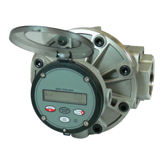
Medium capacity positive displacement flowmeters
I N S T R U C T I O N M A N U A L
Models : OM025, OM040 & OM050
Advertisement
Table of Contents

Related Manuals for Flomec OM040


Summarization of Contents
General (1.0)
Overview (1.1)
Describes the FLOMEC Oval Gear meter and its capabilities.
Operating Principle (1.2)
Explains how the Oval Gear meter works using rotating rotors.
Model Number Information (1.3)
Details how to interpret the meter's model number coding.
Specifications (1.4)
Lists the technical specifications for the flowmeters.
Installation (2.0)
Mechanical Installation (2.1)
Covers aspects of physically installing the flowmeter.
Orientation (2.1.1)
Specifies the correct rotor shaft orientation for mounting.
Flow Conditioning & Locations (2.1.2)
Advises on strainers, pipe runs, and placement.
Electrical Installation (2.2)
Details the wiring requirements for the flowmeter.
Maintenance (4.0)
Disassembly of Pulse Meter (4.1)
Steps for taking apart the basic pulse meter.
Disassembly of Meters Fitted with an Instrument (4.2)
Steps for disassembling meters with integral instruments.
Exploded View & Spare Parts (4.3)
Shows a diagram and lists spare parts for the meter.
Re-assembly of Meter (4.5)
Instructions for correctly reassembling the meter.
Fault Finding (5.0)
Trouble Shooting (5.1)
Provides specific solutions for common meter problems.
Installation (2.0)
Mechanical Installation (2.1)
Covers pre-installation checks and physical mounting.
Orientation (2.1.1)
Specifies the correct rotor shaft orientation for mounting.
Flow Conditioning and Locations (2.1.2)
Advises on strainers, pipe runs, and placement.
Electrical Installation (2.2)
Details the electrical wiring requirements.
Installation (2.0)
Hazardous Area Wiring (2.2.2)
Provides guidance for wiring in hazardous environments.
Pulse Output Selection (2.3)
Explains the various pulse output options.
Hall Effect Sensor Pulse Output (2.3.1)
Details the NPN open collector Hall effect sensor output.
Reed Switch Pulse Output (2.3.2)
Describes the voltage-free reed switch pulse output.
Installation (2.0)
Meters Fitted with Integral Instruments (2.4)
Discusses meters equipped with internal totalizers or controllers.
Meter Calibration Factor (K or Scale Factor) (2.4.1)
Explains the calibration factor used for meters.
Maintenance (4.0)
Disassembly of Pulse Meter (4.1)
Step-by-step guide to disassembling the pulse meter.
Disassembly of Meters Fitted with an Instrument (4.2)
Instructions for disassembling meters with integral instruments.
Maintenance (4.0)
Inspection (4.4)
Guidance on inspecting meter components like O-rings and rotors.
Re-assembly of Meter (4.5)
Instructions for reassembling the meter correctly.
Need help?
Do you have a question about the OM040 and is the answer not in the manual?
Questions and answers