
Related Manuals for Flomec D-40


Summary of Contents for Flomec D-40
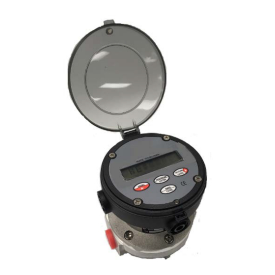
- Page 1 OVAL GEAR Medium Capacity positive displacement Pulse flowmeters I N S T R U C T I O N M A N U A L Model: 1/2” (D-40)
-
Page 2: Table Of Contents
Index / contents 1.0 General Page Overview Operating principal Specifications 2.0 Installation Mechanical installation 2.0.1 Meter & totaliser orientation Flow conditioning & locations Electrical Installation 2.2.1 Instrument Cable 2.2.2 Hazardous Area Wiring Pulse output selection for pulse meters 2.3.1 Hall effect sensor output 2.3.2 Reed switch output Calibration K-factor... -
Page 3: General
General 1.1 Overview The Oval Gear meter is a precise positive displacement flowmeter incorporating a pair of oval geared rotors. These meters are capable of measuring the flow of a range of clean liquids such as fuels, fuel oils & lubricating liquids. -
Page 4: Specifications
Specifications 1.3 Specifications D-40 Model Prefix Nominal size (Inches) 15mm (1/2") *Flow range - (LPM) Litres/min 1 ~ 40 - (GPM) USGal/min 0.26 ~ 10.6 Accuracy @ 3cp ±0.5% Repeatability typically ±0.03% of reading Temperature range -20⁰C ~ +80⁰C (-4⁰F ~ +176⁰F) Maximum pressure;... -
Page 5: Installation
Installation Mechanical Installation Prior to installing the meter check that : The fluid is compatible with the meter materials of construction using appropriate information such as • fluid compatibility charts and site experience. The application and process conditions are compatible with the meter specifications. Minimum and •... -
Page 6: Meter & Totaliser Orientation
Installation 2.1 Meter & totaliser orientation The flowmeter MUST be mounted so that the rotor shafts are in a horizontal plane. This is achieved by mounting the meter so that the digital display is facing the user in a horizontal direction, it should never point towards the sky or towards the ground. -
Page 7: Instrument Cable
Installation 2.2.1 Instrument Cable Twisted pair low capacitance shielded instrument cable 7 x 0.3mm (0.5mm²) should be used for electrical connection between the flowmeter and remote instrumentation, use Belden® number 9363 or similar. The cable drain or screen should be terminated on a DC COMMON or a specifically assigned shield termination at the readout instrument end only in order to protect the transmitted signal from mutual inductive interference. -
Page 8: Commissioning
Commissioning Commissioning Once the meter has been mechanically installed the meter is ready for commissioning. The meter must NOT be run until the pipework is flushed of foreign matter, more often than not foreign matter is present after pipework fabrication or modification; weld slag, grinding dust, sealing tape & compound &/or surface rust are most common offenders. -
Page 9: Maintenance
Maintenance Maintenance Adhering to the installation instructions in this manual should ensure your meter provides the required operational performance. The mechanical operation of these meters requires a periodic maintenance and inspection regime to maximize the operational availability of the meter. The frequency of maintenance depends on the application factors including liquid lubricity, abrasiveness and operational factors such as flowrate and temperature. -
Page 10: Inspection
Maintenance Inspection (refer Exploded View) Inspect O-rings (3) for damage, chemical attack, deformity or any form. Remove, inspect & clean the rotors (2), check that the primary rotor gear pinion for any damage. Check the measuring chamber (1) for damage or scoring & redress if necessary, the rotor shafts should NOT be loose or able to be rotated. -
Page 11: Spare Parts List
Maintenance 4.4 Spare Parts D-40 Part No. Item Description Body / shaft assembly 1401098 (BSP) Body / shaft assembly (E and I Registers) 1401128 (NPT) Rotor assembly set 1524049 Electronic rotor set Body O-ring BS150V Body O-ring Meter cap 1302129... -
Page 12: Fault Finding
Fault finding Fault Finding Pulse meters have two distinct sections: the mechanical wetted section housing the rotors and the electrical section housing the pulse output board. Meters fitted with integral instruments have these two sections plus the instrument. The aim of fault finding is to trace the source of the fault to one of these sections. If a fault is traced to an instrument section, refer to the relevant instruction manual. -
Page 13: Trouble Shooting
Trouble shooting 5.1 TROUBLE SHOOTING Symptom Possible cause Solution Output signal 1. Ground shield of signal cable 2. Re-route cable from high electrical energy sources interference Entrained air or 1. Remove source of air or gas entrapment Meter 2. Install an upstream air eliminator readings Pulsating flow are high... - Page 14 Notes:...
- Page 15 The oil used is Castrol Diesel Calibration Fluid 4113 (product code 055830). © 2017 Great Plains Industries, Inc., All Rights Reserved. Great Plains Industries, Inc. / 888-996-3837 / FLOMEC.net IM-D-40 - Pulse 3216...
Need help?
Do you have a question about the D-40 and is the answer not in the manual?
Questions and answers