Advertisement
BS-1632, BS-1634, BS-1636
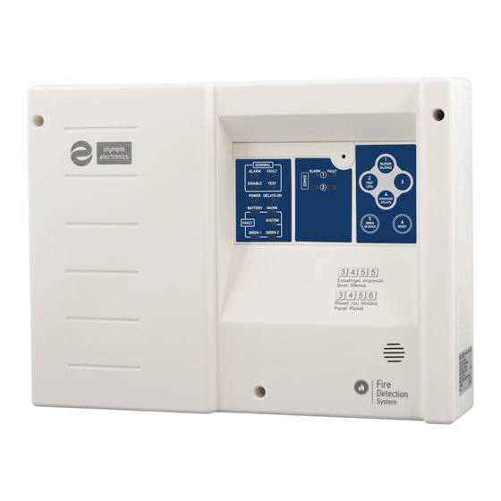
Conventional 2, 4 and 6 zone Fire Alarm Panels
GENERAL
The family of fire detection panels consist of 3 types (2, 4 and 6 zone) with identical operation and indications. The panels have
2 independent siren outputs, Alarm, Fault Relay and a programmable AUX relay. The required batteries for the panels are two
A-920 (12V/2.6Ah). All functions and indications are according to European Norms EN 54-2 and EN 54-4.
Battery compartment
two Α-920
Page 1 from 10
Thank you for your trust in our products
Olympia Electronics - European manufacturer
Extra earth
Mounting hole
terminals
Figure 1. Schematic diagram of the panel
Top cover
retaining screws
Control Keyboard and
indication leds
Mains voltage connection
terminal block (220-240V AC)
Mounting holes
General output connection
(Sirens,24V)
Zone connection terminal
MODE selection
microswitch
Relay outputs
connection terminals
921163600_09_022
Advertisement
Table of Contents

Related Manuals for olympia electronics BS-1634


Summarization of Contents
Indication LED Description
General Indicator Lights
Overview of general indicator lights like Power, Delays ON, and System fault.
Fault and Battery Indicators
Details on fault indication LEDs for Battery, Mains, and System status.
Control Keyboard Operation
Access Level 1 Functions
Functions available without a code, like buzzer silence and lamp test.
Access Level 2 Functions
Evacuate, Siren Silence, and Panel Reset
Procedures for evacuate, silencing sirens, and resetting the panel.
Zone and Siren Enable/Disable
Method to enable or disable specific zones or sirens.
Delay ON/OFF Control
How to enable or disable output delays on the panel.
Access Level 3 Functions
AUX Relay Programming
Programming the behavior of the Auxiliary Relay based on zone conditions.
Connections Overview
Connecting Detectors and Call Points to Zones
Wiring detectors and call points to panel zone terminals, including resistor placement.
Zone Wiring Requirements
Cable length, cross-section, and insulation requirements for zone connections.
Other Panel Outputs
24V Outputs (24V_M, 24V_P)
Details on the 24VDC outputs for specific device power.
Relay Outputs (Alarm, Fault, AUX)
Information on voltage-free relay contacts for signaling.
Panel Installation Guidelines
Mounting and Cabling
Procedures for physically mounting the panel and running cables.
Mains Power and Battery Connection
Instructions for connecting the panel to mains power and backup batteries.
Initial Installation and Testing
Initial Setup and Mode Switch
Steps for initial panel setup and using mode switches.
Walk-Testing Procedure
Method for testing system functionality using walk-test mode.
Optional EN 54-2 Functions and Design
Information on optional EN 54-2 features and component design.
Technical Specifications
Panel Power and Battery Details
Covers mains supply, consumption, battery type, charging, autonomy, and cut-off voltage.
Circuit and Output Specifications
Details zone circuits, alarm circuits, 24P, 24M, and relay outputs.
Physical and Environmental Ratings
Includes IP rating, cables, fuses, temperature, humidity, material, dimensions, and weight.
Compliance and Warranty
Information on standards compliance and product guarantee period.
Need help?
Do you have a question about the BS-1634 and is the answer not in the manual?
Questions and answers