
Subscribe to Our Youtube Channel
Related Manuals for olympia electronics BS-316


Summary of Contents for olympia electronics BS-316
- Page 1 BS-304, BS-308, BS-312, BS-316 Gas detection control panel up to 16 inputs Installation – operation manual Page 1 from 22 921316000_09_016...
-
Page 2: Table Of Contents
Information menu ........................16 Parameters menu ........................17 Enable menu ........................19 Disable menu ........................19 Check menu ......................... 19 Useful notes to setup the panel BS-316 ..................20 Technical Characteristics ---------------------------------------------------------------------------------------- 20 Record Setup ........................22 Page 2 from 22 921316000_09_016... -
Page 3: Operation Instructions
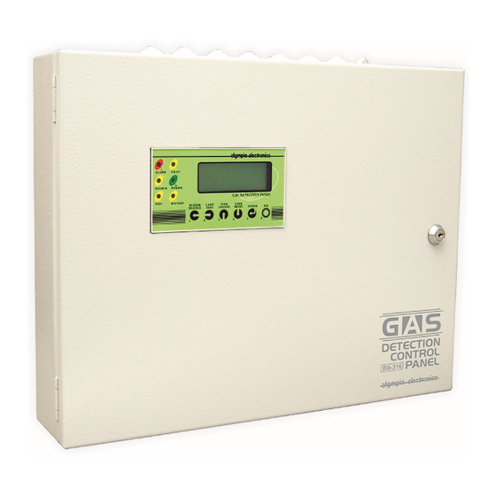
Description The BS-316 is a gas detection panel with 16 inputs. On each input it can be connected only one gas detector 4-20 Indications and Controls The panel incorporates one liquid crystal display (LCD) and a series of indication LEDs that informs the user about its status. -
Page 4: Access Level 1
(lamp test) is pressed the system conducts a sequential LED and Display test. When the system is in quiescence state, the lcd screen shows info about the system. The below screen shows some information about the system OLYMPIA ELECTRONICS BS-316 V.055... -
Page 5: Events Menu
1.3.1 Events Menu All the events of the system can be shown by pressing the key “3” View Events and then the key Enter. This screen on the left shows that the system has recorded 59 events. The ALARM 1 ( 59/ 59) event shown in the example shows that this event is a ALARM 2 of the 4th 15%LIE S= 4... -
Page 6: Installation Instructions
Mounting The mounting of panel must be in a visible place with easy access by the users. The panel BS-316 is a product for easy wall mounting and indoor use. The mounting on the wall can be done by using plugs and screws that are included in the panel package. -
Page 7: Description Of The Internal Parts Of The Panel
The battery can be placed on the bottom side of the panel. The battery Α-986 of olympia electronics can be used. The charging circuit of the panel is also calculated for the specific battery type. In case of replacement, the new battery must be of the same type. -
Page 8: Sensor Connectivity
Figure 3: Power cable Sensor connectivity Before connecting any sensor to the panel, the main power supply must be disconnected. There are two ways of connect the sensors depending on the number of contacts. Α) Sensor with 2 contacts 4÷20mA The connection of sensors with 2 contacts 4÷20mA must be between «+»... - Page 9 The connection of sensors with 3 contacts 4÷20mA, must be between «+», «-» and “S” of sensor that correspond to «+», «-» and “S” of panel as shown in figure 5. B S-39 0 Figure 5: Connection diagram with three pad sensor The cross-section of the cable depends on the cable length (see next table).
-
Page 10: Output Connectivity
Finally on the AUX input we can connect fire detection buttons between inputs «-» and “S” of (Figure 6). Figure 6: Connection device diagram on helpful input. Figure 7: Connection diagram for BS-531. Output connectivity On the panel there are 16 programmable outputs relay. Each relay has a triple connector NO, NC, C. For more information about output setup see paragraph 2.7.1. -
Page 11: Other Outputs And Their Use
Other outputs and their use The panel has the following outputs: Output AUX. This is an auxiliary power output (between «-» and «+») that has the capability of providing 20Vdc for maximum load of 300mΑ. Connectors F_OUT. Open collector output. If there is a general fault (Fault) it is enabled (0V). NOTE The maximum drawn from output “AUX”... -
Page 12: Technician Menu
Technician menu Access Technician menu All the functions of access level 3 can be accessed from the menu that displayed when we press button “5" in the technician menu. The panel prompts for the technician code ==================== TYPE TECHNICIAN CODE ---- ==================== The technician code is 2-3-3-3. -
Page 13: Configuration
Configuration In the configuration menu the technician can configure the sensors, the relays and the zones. Sensor configuration The available options in the configuration sensor menu, are shown below, ===== SENSORS ===== ===== SENSORS ===== ===== SENSORS ===== DELETE SENSOR SETUP SENSOR COPY SENSOR SELECT ENTER... -
Page 14: The Parameter Increase Must Be Set To No
The variables above are: NAME: the name of the sensor. You can put up to 20 characters. UNIT: Units to meter the gas. There are two kinds of units in ppm or %LIE or %. INCREASING: if the value is increasing or decreasing. ZERO: Minimum (start up of scale). -
Page 15: Zones Configuration
SETUP RELAY SETUP RELAY DELAY ON 0..250 0..250 COPY RELAY DELAY OFF TIME ON 0..250 INITIALIZE RELAY LOGIC CONTACT POSITIVE NEGATIVE LATCHED OUTPUT NO YES SAVE RELAY? Figure 7: Diagram menu setup relay The above diagram shows the menu for the configuration of a relay: The parameters are: DELAY ON : it is the delay time (max 250 seconds) of the output activation from the moment when the gas concentration is in the alarm setting. -
Page 16: Information Menu
SETUP ZONE RELAY ON ALARM1 1..17 RELAY ON ALARM2 1..17 1..17 RELAY ON ALARM3 RELAY ON FAULT 1..17 SAVE ZONE 1..17 Figure 12: Diagram menu of the zone configuration Information menu From this selection the technician can be informed for all the system. The below diagram shows the menu INFORMATION SENSORS RELAY... -
Page 17: Parameters Menu
The right screen shows the ZERO, RANGE, ALARM1, ALARM2,ALARM3, RELAY ON ALARM1, RELAY ON ALARM2, RELAY ON ALARM3, RELAY ON FAULT and ZONE respectively. To change the sensor, use the button “3” or “4”. An example of the information relay screen is ==== RELAY 2 ======= D0= 10 DF= 40 TO=20 LOGIC = NO... - Page 18 Figure 9: Parameters menu The selections are: SCREEN BACKLIGHT: “CONTINUOUS” means that the screen panel is lighting continually (this selection reduces the autonomy of the system) “NO CONTINUOUS” means the backlight of the display will be ON when there are events or one button is pressed.
-
Page 19: Enable Menu
Enable menu The enable menu is used to enable a sensor or all the sensors: === ENABLEMENT ==== === ENABLEMENT ==== ENABLE A SENSOR ENABLE ALL SENSORS SELECT → ENTER SELECT → ENTER ==================== ==================== Disable menu The disable menu is used to disable a sensor or all the sensors: === DISABLEMENT === DISABLEMENT DISABLE A SENSOR... -
Page 20: Useful Notes To Setup The Panel Bs-316
Useful notes to setup the panel BS-316 For the correct mounting and setup of the panel BS-316, the user must do some basic steps: 1) First of all, the technician has to design the schematic which includes the way of installation of the panel and the devices, the length of the cable and the point where the device is connected. - Page 21 Olympia Electronics guarantees the quality, condition and operation of the goods. The period of warranty is specified in the official catalogue of Olympia Electronics and also in the technical le aflet, which accompanies each product. This warranty ceases to exist if the buyer does not follow the...
-
Page 22: Record Setup
Record Setup We suggest completing the next tables for your setup and keep them for future reference. Title : …........................ Sensor’s Model ZERO RANGE UNIT Alarm 1 OUTPUT 1 Alarm 2 OUTPUT 2 Alarm 3 OUTPUT 3 DELAY ON DELAY OFF TIME ON POSITIVE (YES/NO) LATCHED...
Need help?
Do you have a question about the BS-316 and is the answer not in the manual?
Questions and answers