
Related Manuals for olympia electronics GR-750 Series


Summary of Contents for olympia electronics GR-750 Series
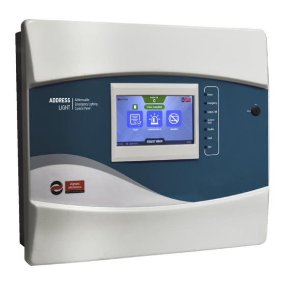
- Page 1 GR-750x series Control panels for addressable emergency luminaires Quick installation guide...
-
Page 2: Table Of Contents
Document number: GR-750x series 923750400_90_001_EN Control panel for addressable emergency luminaires Date: 25/5/2023 Page: 2 of 15 Contents INTRODUCTION ............................3 General description ..........................3 Safety ............................... 3 Terms and definitions ..........................4 1.3.1 Point ..............................4 1.3.2 Emergency mode/In emergency ...................... 4 1.3.3 Inhibit mode ............................. -
Page 3: Introduction
Document number: GR-750x series 923750400_90_001_EN Control panel for addressable emergency luminaires Date: 25/5/2023 Page: 3 of 15 1 Introduction 1.1 General description The GR-750x series of control panels for addressable emergency luminaries consists of four models: (GR- 7501, GR-7502, GR-7503 and GR-7504 with 1, 2, 3 and 4 loop circuits respectively). All share the same interface, functionality, and indicators. -
Page 4: Terms And Definitions
Document number: GR-750x series 923750400_90_001_EN Control panel for addressable emergency luminaires Date: 25/5/2023 Page: 4 of 15 1.3 Terms and definitions 1.3.1 Point The term “point” refers to any addressable device connected to the panel. For example, an emergency luminaire. 1.3.2 Emergency mode/In emergency When the system or a point is referred as being in emergency or emergency mode, it means that its mains power supply is unavailable, and it is operating by drawing power from its battery. -
Page 5: Installation
Document number: GR-750x series 923750400_90_001_EN Control panel for addressable emergency luminaires Date: 25/5/2023 Page: 5 of 15 2 INSTALLATION 2.1 Mounting the panel WARNING All installation operations must be done while the panel is disconnected from mains power supply and batteries. Only trained personnel should carry out operations inside the panel and only after taking all the precautionary measures. -
Page 6: Power Supply Connection
Document number: GR-750x series 923750400_90_001_EN Control panel for addressable emergency luminaires Date: 25/5/2023 Page: 6 of 15 2.2 Power supply connection The power supply cable must be a 3−core double insulated wire that meets the voltage and current requirements of the panel. The ground terminal (marked with on the power management board) must be connected to the installation’s ground (protective earth) to ensure proper and safe operation of the system. -
Page 7: Point Wiring
Document number: GR-750x series 923750400_90_001_EN Control panel for addressable emergency luminaires Date: 25/5/2023 Page: 7 of 15 2.3 Point wiring Use a cable that meets the specifications below to connect the loop board with the points: 1. The installation cable must be suitable for data transfer. 2. - Page 8 Document number: GR-750x series 923750400_90_001_EN Control panel for addressable emergency luminaires Date: 25/5/2023 Page: 8 of 15 The below figure describes the parallel connection of addressable points, which use a 2-way terminal, with the loop board: Notes: • Max 250 points per loop device •...
-
Page 9: Configure Point Address
Document number: GR-750x series 923750400_90_001_EN Control panel for addressable emergency luminaires Date: 25/5/2023 Page: 9 of 15 2.4 Configure point address A valid (1-250) and unique address (per loop) must be set for each point, using the onboard address selection DIP switch on each point. -
Page 10: Wiring Verification
Document number: GR-750x series 923750400_90_001_EN Control panel for addressable emergency luminaires Date: 25/5/2023 Page: 10 of 15 2.5 Wiring verification IMPORTANT The following steps should be performed while the cables are NOT connected to the loop board terminals. Steps to verify the integrity of the installation’s wiring: 1. -
Page 11: Panel Configuration
Document number: GR-750x series 923750400_90_001_EN Control panel for addressable emergency luminaires Date: 25/5/2023 Page: 11 of 15 3 PANEL CONFIGURATION 3.1 Installation procedure • Mount the panel • Check each loop cable for correct polarity and open/short circuit. • Configure a valid and unique address for each point, on each loop. •... -
Page 12: Troubleshooting
Document number: GR-750x series 923750400_90_001_EN Control panel for addressable emergency luminaires Date: 25/5/2023 Page: 12 of 15 3.2 Troubleshooting FAULT SOURCE CAUSE ACTION The batteries of the panel are not • Check the batteries connected or faulty. connections. Disconnected BATTERY •... - Page 13 Document number: GR-750x series 923750400_90_001_EN Control panel for addressable emergency luminaires Date: 25/5/2023 Page: 13 of 15 1. Luminaire has no power. • Verify the operation of the 2. Luminaire has been removed. luminaire. Inspect for internal 3. EMI (electromagnetic faults and faulty loop wiring.
- Page 14 Document number: GR-750x series 923750400_90_001_EN Control panel for addressable emergency luminaires Date: 25/5/2023 Page: 14 of 15 LOOP The specific component/point • Check the connection between has been disconnected from the the panel and the specific Disconnected panel. component/point. POINT PRINTER There is an open circuit detected •...
- Page 15 Declaration of Conformity Olympia Electronics N. Lakasas - P. Arvanitidis S.A. hereby declares that this product complies with the radio equipment directive 2014/53/EU (RED) and therefore has been marked with the symbol .
Need help?
Do you have a question about the GR-750 Series and is the answer not in the manual?
Questions and answers