
Subscribe to Our Youtube Channel
Related Manuals for olympia electronics BS-746


Summary of Contents for olympia electronics BS-746
- Page 1 S A A R CERTIFICATE VALID SYSTEM www.olympia-electronics.gr EN ISO 9001 : 2008...
-
Page 2: Table Of Contents
CONTENTS INTRODUCTION 2. PART TYPES 3. COMPOSING A COMPLETE SYSTEM. 3.1. Systems up-to 48 zones-rooms. 3.2. Systems from 49 to 240 zones -rooms. 3.3. System with many keyboards (repeaters). DESCRIPTION OF KEYS AND INDICATIONS. 5. ACCESS CODES 6. PROGRAMMING 6.1. PRO. Rooms - Zones programming. 6.2. -
Page 3: Introduction
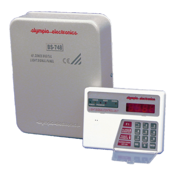
Usually the BS-748 main panel is mounted in a place which is not visible (e.g. store, cupboard) and BS-746 control keyboard is mounted in a place which is visible and has easy access (e.g. RECEPTION). When a call is issued the the display on the keyboard shows us the room number that issued the call. - Page 4 5 BS-746 BS-748 (slave) address 6 BS-748 (slave) address 7 BS-748 (slave) address 8 Fig2. BS-748 (slave) Connections shematic diagram with one keyboard BS-746 and 5 address 9 panels BS-748 signal numerator panel 48-240 zones Page 4 from 18 921746000_09_003...
- Page 5 BS-748 (slave) BS-746 address 7 (slave) address 3 BS-748 (slave) BS-746 address 8 (slave) address 4 BS-748 (slave) address 9 Fig3. Connection diagram with4 keyboards BS-746 and 5 panels BS-748 for a complete enumerator panel system. Page 5 from 18 921746000_09_003...
- Page 6 4. KEYBOARD DESCRIPTION. KEYS 4.1. The numeric keys 1, 2, 3, 4, 5, 6, 7, 8, 9, 0 are used to enter numbers. 4.2. The ESC key is used for cancelling and operation or exiting a menu. 4.3. The ENTER key is used to confirm an operation. 4.4.
-
Page 7: Access Codes
5. ACCESS CODES User code (0000). Using this code we can reset all calls accepted by the panel. The default value is (0000) Technical code (1111). Using this code we can access the programming menu. The default value is (1111) Reset code (9946). - Page 8 If we want to change the keyboard address we must type in the required number (1 to 4 according to the address selection table shown below) and at the end press the ENTER key for the new value to be accepted. At the end of the process press successively the ESC key to exit programming mode.
-
Page 9: Buzz
6.2.3 buzz. Buzzer sound mode and mode operation system. With this programming operation we can change the sound mode of the buzzer when there is a call. Insert the technical code (1111) and using the key FAULT EVENTS scroll to the indication S-UP, press the ENTER key and scroll to the indication buzz using the arrow keys. -
Page 10: Ccod
6.2.5 Ccod. Changing the user code (0000=default) Insert the technical code (1111) and using the FAULT EVENTS key scroll to the indication S-UP. Press the ENTER key and use the arrow keys to scroll to the indication Ccod, then press the ENTER key so the indication 0000 is shown on the display. -
Page 11: Dloa
6.2.7. dLoA. Updating data on repeater keyboards using the master keyboard. This programming operation is used to transfer the programmed rooms from the central keyboard(master) to the repeaters keyboards. It is used only when we have repeater keyboards connected to the system. Insert the technical code (1111) and use the FAULT EVENTS to scroll to the indication S-UP, press the ENTER key and using the arrow keys scroll to the indication dLoA, then press the ENTER key and the programmed rooms will be transferred from the... -
Page 12: Test
6.3. TEST. System check , call point and programming names Insert the technical code (1111) and using the FAULT EVENTS key scroll to the indication TEST. Press ENTER and the Display shows the indication ------. In this mode we can test the system and check if the call points which are mounted on every room are operating and corresponding to the numbers that we have programmed for every room. - Page 13 7.5. Resetting/cancelling all calls using the user code. In order to be able to cancel all the calls using the user code we must enable this operation. To reset all calls using the user code simply insert the user code (e.g. 0000). In this case all the calls will be canceled simultaneously .
- Page 14 Connect the panel BS-748 to the main power supply(230V AC). Isolate the mains power supply before doing any connections. Connect the keyboard BS-746 with 4 wires to the panel BS-748 (+, - used for supply purposes , +A, -A used for communication purposes)
-
Page 15: Main Menu
BS-746. TECHNICAL MENU MAIN MENU INDICATION TECHNICAL ACCESS CODE 1111 PROGRAMMING SETUP TEST MENU MENU MENU INDICATION INDICATION INDICATION 0 Does not communicate 1 (default) operates as central keyboard (master) (U1) 2 operates as repeater keyboard (U2) 3 operates as repeater keyboard... - Page 16 Call point Call point Call point Call point Call point Call point Page 16 from 18 921746000_09_003...
- Page 17 Call point Call point Call point Call point Call point Call point The call points that are connected to the terminal blocks 8-24 are connected in the same manner as the call points on the terminal blocks 1-7 The call points that are connected to the terminal blocks 25-43 are connected in the same manner as the call points on the terminal blocks 44-48 230V AC...
- Page 18 Page 18 from 18 921746000_09_003...
Need help?
Do you have a question about the BS-746 and is the answer not in the manual?
Questions and answers