
Related Manuals for olympia electronics GR-6500


Summary of Contents for olympia electronics GR-6500
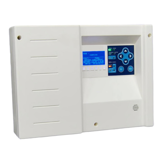
- Page 1 LIGHTING Emergency lighting addressable panel GR-6500 Quick Installation Guide & Generic Design 923650001_90_004...
-
Page 2: Specifications
- Pliers network, but also for each luminaire individually. - Cutter The ease of access of GR-6500 helps you to retrieve information and control the system light MAINTENANCE network with simple actions as well as remotely The periodical checks must follow the EN50172 via Ethernet. -
Page 3: Mounting The Panel
PREREQUISITE REQUIREMENTS AND PRELIMINARY PROCEDURES Addressable Luminaire Connections • 16 available Zones. • The GR-6500 can support up to 250 points. • The maximum connected points to each LOOP must not exceed the 150. • Each point must have unique non repeatable address. - Page 4 Correct cable and connection • The installation cable must be suitable for data transfer. • We recommend: - LiYCY - YSLY-OZ • The communication cables must be placed 40cm away from any MAINS cable. • The communication cables must be placed 5m away from any motors or power station. •...
- Page 5 • If 4 contacts on the communication terminal blocks, the L+ are linked together as well as the L-. +L -L +L -L Point 1 Point 2 Point 3 Point 4 Point 5 + L -L + L -L + L -L + L -L + L -L + L -L...
- Page 6 • In- line topology(or Star). Note: Max. 75 points per line / Max 250points in total. Point Point Point Point Point Point Point Point Point Point Point Point STEP BY STEP INSTALLATION ISTRUCTIONS • Mount the panel on a surface, able to support 10Kgs at least. •...
-
Page 7: Installation Procedure
INSTALLATION PROCEDURE •Set the address of each luminaire, setting up the DIP switch inside of the luminaire. PREPARATION • Certain models, such as ZLD-34, do not contain DIP switches. In this case, the address should be set through the panel, connecting and setting the luminaires one- by-one. - Page 8 •FIND ALL POINTS to register all the points to the panel. TECHNICIAN MENU <SYSTEM> •Assign a Zone for each point.(Optional). TECHNICIAN MENU <POINTS> •Program FUNCTION TEST. TECHNICIAN MENU •Program CAPACITY TEST. TECHNICIAN MENU •Set ETHERNET PCB. Enable or Disable the ethernet adaptor GR-8530. If applicable. TECHNICIAN MENU <NETWORK>...
-
Page 9: Troubleshooting
TROUBLESHOOTING FAULT PROBABLE CAUSE ACTION THE PANEL REPORTS: The internal battery of the panel is not Connect the battery. «PANEL connected DISCONNECTED BATTERY» THE PANEL REPORTS: Re execute the automatic point «POINT Χ,WRONG 1) The luminaire type was changed in recognition via the technician menu the specific address. - Page 10 THE PANEL FINDS Find the open circuit, between the ONLY CERTAIN 1) There is an open circuit in the last detected point and the first un communication line. If the LUMINAIRES detected. To easily see the connection is done using the loop communication indication go to topology then there might be MENU>TEST>POINTS IN TEST and by...
Need help?
Do you have a question about the GR-6500 and is the answer not in the manual?
Questions and answers