
Related Manuals for olympia electronics GR-750 Series


Summary of Contents for olympia electronics GR-750 Series
- Page 1 GR-750x series Control panels for addressable emergency luminaires Specifications Installation Configuration Operation READ THIS MANUAL PRIOR TO ANY OPERATION...
-
Page 2: Table Of Contents
GR-750x series Document number: 923750400_09_007 Control panel for addressable emergency Date: 3/5/2022 Page: 2 of 71 luminaires Contents INTRODUCTION .......................... 7 General description ..........................7 Safety ..............................7 Terms and definitions ........................... 8 1.3.1 Point ..............................8 1.3.2 Emergency mode/In emergency ...................... 8 1.3.3 Inhibit mode ............................. - Page 3 GR-750x series Document number: 923750400_09_007 Control panel for addressable emergency Date: 3/5/2022 Page: 3 of 71 luminaires 3.4.1 Panel network fault examples ......................23 Relays ..............................24 Inputs ..............................25 Outputs ..............................26 Configuration software (PC-7500) ...................... 27 Printer paper replace ........................... 28 HOME SCREEN .........................
- Page 4 GR-750x series Document number: 923750400_09_007 Control panel for addressable emergency Date: 3/5/2022 Page: 4 of 71 luminaires 5.2.6 OUTPUTS ............................43 5.2.7 RELAYS ............................43 5.2.8 PRINTER ............................44 5.2.9 ANNUAL CHECK DONE ....................... 44 SETUP ..............................45 5.3.1 CONFIGURE POINT ........................46 5.3.2 FIND ALL POINTS .........................
- Page 5 GR-750x series Document number: 923750400_09_007 Control panel for addressable emergency Date: 3/5/2022 Page: 5 of 71 luminaires 6.4.13 LUMINAIRE COMMANDS ......................69 TEST LED INDICATORS ........................69 APPENDIX ..........................70 List of compatible luminaire models ....................70...
- Page 6 GR-750x series Document number: 923750400_09_007 Control panel for addressable emergency Date: 3/5/2022 Page: 6 of 71 luminaires List of tables Table 1 - Technical specification table ........................ 9 Table 2 – LED indicators ........................... 10 Table 3 – Panel relays ............................12 Table 4 –...
-
Page 7: Introduction
GR-750x series Document number: 923750400_09_007 Control panel for addressable emergency Date: 3/5/2022 Page: 7 of 71 luminaires 1 Introduction 1.1 General description The GR-750x series of control panels for addressable emergency luminaries consists of four models: (GR-7501, GR-7502, GR-7503 and GR-7504 with 1, 2, 3 and 4 loop circuits respectively). All share the same interface, functionality, and indicators. -
Page 8: Terms And Definitions
GR-750x series Document number: 923750400_09_007 Control panel for addressable emergency Date: 3/5/2022 Page: 8 of 71 luminaires 1.3 Terms and definitions 1.3.1 Point The term “point” refers to any addressable device connected to the panel. For example, an emergency luminaire. 1.3.2 Emergency mode/In emergency When the system or a point is referred as being in emergency or emergency mode, it means that its mains power supply is unavailable, and it is operating on power supplied by its battery. -
Page 9: Technical Specification
GR-750x series Document number: 923750400_09_007 Control panel for addressable emergency Date: 3/5/2022 Page: 9 of 71 luminaires 1.4 Technical specification Table 1 - Technical specification table GR-750x panel series Description GR-7501 GR-7502 GR-7503 GR-7504 Loop circuits 400mA max. current per loop, 250 addresses/addressable points per loop Mains power supply voltage 220-240 Vac, 50/60Hz Mains maximum current... -
Page 10: System Description
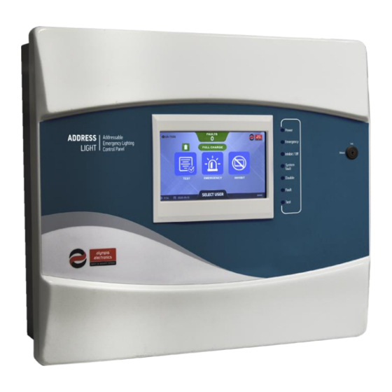
GR-750x series Document number: 923750400_09_007 Control panel for addressable emergency Date: 3/5/2022 Page: 10 of 71 luminaires 2 System description 2.1 Control panel fascia Figure 1 2.1.1 LED indicators The LEDs indicate when there are certain important statuses active, while more detailed information is displayed on the screen. -
Page 11: Lcd Screen
GR-750x series Document number: 923750400_09_007 Control panel for addressable emergency Date: 3/5/2022 Page: 11 of 71 luminaires 2.1.2 LCD screen The panel is equipped with a 7” TFT LCD touch screen display which can be used to control the panel and provide information to the user. -
Page 12: Panel Relays
GR-750x series Document number: 923750400_09_007 Control panel for addressable emergency Date: 3/5/2022 Page: 12 of 71 luminaires 2.3 Panel relays Panel has four relays located on the power management board marked AUX, FAULT, SUPPLY and OPER. The behavior of the operation (OPER), supply (SUPPLY) and fault (FAULT) relays is predefined and cannot change. -
Page 13: Luminaire Commands
GR-750x series Document number: 923750400_09_007 Control panel for addressable emergency Date: 3/5/2022 Page: 13 of 71 luminaires 2.6 Luminaire commands A list of the commands the panel can sent to the luminaires can be found below, along with the description of each command. -
Page 14: Panel Network
GR-750x series Document number: 923750400_09_007 Control panel for addressable emergency Date: 3/5/2022 Page: 14 of 71 luminaires 2.9 Panel network The panels of the GR-750x series can be connected and form a network of panels, referenced as “Panel network”, using the NET-L and NET-R terminals on the power management board. The maximum number of connected panels cannot exceed 24. -
Page 15: Installation
GR-750x series Document number: 923750400_09_007 Control panel for addressable emergency Date: 3/5/2022 Page: 15 of 71 luminaires 3 INSTALLATION 3.1 Installation/Maintance WARNING All installation operations must be done while the panel is disconnected from mains power supply and batteries. Only trained personnel should carry out operations inside the panel and only after taking all the precautionary measures. -
Page 16: Control Panel Installation
GR-750x series Document number: 923750400_09_007 Control panel for addressable emergency Date: 3/5/2022 Page: 16 of 71 luminaires 3.2 Control panel installation 3.2.1 Interior of the panel To access the interior of the panel, first unlock the key lock on the front of the panel with the key included in the panel’s package. -
Page 17: Mounting The Panel
GR-750x series Document number: 923750400_09_007 Control panel for addressable emergency Date: 3/5/2022 Page: 17 of 71 luminaires Inside the main body of the metal housing (Figure 6) are located the power supply unit (left), the power management board (MAIN board), the loop boards (center), the battery area for the two batteries (bottom), the earth bar terminal (left), the panel mounting holes and the cable openings. -
Page 18: Connecting The Mains Power Supply Cables (220-240V Ac )
GR-750x series Document number: 923750400_09_007 Control panel for addressable emergency Date: 3/5/2022 Page: 18 of 71 luminaires 3.2.3 Connecting the mains power supply cables (220-240V IMPORTANT 1. Any installation, repair or electrical equipment maintenance operation must be executed with both mains power supply and batteries disconnected. 2. -
Page 19: Point Wiring
GR-750x series Document number: 923750400_09_007 Control panel for addressable emergency Date: 3/5/2022 Page: 19 of 71 luminaires 3.3 Point wiring Use a cable that meets these specifications, to connect the loop board with the points: 1. Two−core shielded twisted pair cable. If the cable is unshielded, the communication between the loop and the points is susceptible to electromagnetic interferences. - Page 20 GR-750x series Document number: 923750400_09_007 Control panel for addressable emergency Date: 3/5/2022 Page: 20 of 71 luminaires Figure 9 describe the parallel connection of addressable points, which use a 2-way terminal, with the loop board: Figure 9 [20]...
- Page 21 GR-750x series Document number: 923750400_09_007 Control panel for addressable emergency Date: 3/5/2022 Page: 21 of 71 luminaires Figure 10 describe the parallel connection of addressable points, which use a 4-way terminal, with the loop board: Figure 10 [21]...
-
Page 22: Panel Network Wiring
GR-750x series Document number: 923750400_09_007 Control panel for addressable emergency Date: 3/5/2022 Page: 22 of 71 luminaires 3.4 Panel network wiring Table 8 – Panel network specifications Panel network specifications Maximum number of panels Maximum cable length* 800 meters * 2-core shielded twisted pair cable Recommended cable type with stranded wires... -
Page 23: Control Panel For Addressable Emergency
GR-750x series Document number: 923750400_09_007 Control panel for addressable emergency Date: 3/5/2022 Page: 23 of 71 luminaires Figure 12 3.4.1 Panel network fault examples Figure 13 Case 1 (Figure 13): In this case we have 4 panels connected as shown above, using a closed ring topology. If panel P2stopsoperating (goes to cut off, unexpected crash or some other fault) then P1, P3 and P4 panels will continue to communicate with each other. -
Page 24: Relays
GR-750x series Document number: 923750400_09_007 Control panel for addressable emergency Date: 3/5/2022 Page: 24 of 71 luminaires 3.5 Relays There are 4 relays in total, 3 relays for different states of the panel and 1 programmable auxiliary relay. All relays are rated 30Vdc, 5A max. External fuses must be added according to the connected circuit. The terminal connections of each relay are described in the table below: Table 9 –... -
Page 25: Inputs
GR-750x series Document number: 923750400_09_007 Control panel for addressable emergency Date: 3/5/2022 Page: 25 of 71 luminaires 3.6 Inputs Use a separate cable to connect each input. It is recommended to use 2−core shielded cables, not multicore cables. If a shielded cable is used, the cable’s shield must be connected only to the earth bar terminal inside the panel. -
Page 26: Outputs
GR-750x series Document number: 923750400_09_007 Control panel for addressable emergency Date: 3/5/2022 Page: 26 of 71 luminaires 3.7 Outputs Use a separate cable to connect each output. It is recommended to use 2−core shielded cables, not multicore cables. If a shielded cable is used, the cable’s shield must be connected only to the earth bar terminal inside the panel. -
Page 27: Configuration Software (Pc-7500)
GR-750x series Document number: 923750400_09_007 Control panel for addressable emergency Date: 3/5/2022 Page: 27 of 71 luminaires 3.8 Configuration software (PC-7500) The GR750x panel series is supported by the “PC-7500” PC software. It provides a user-friendly graphical interface for configuring and managing all the panel’s settings (download/upload/backup). Software download available at: https://www.olympia-electronics.com/en/support/software PC-7500 requirements: •... -
Page 28: Printer Paper Replace
GR-750x series Document number: 923750400_09_007 Control panel for addressable emergency Date: 3/5/2022 Page: 28 of 71 luminaires Figure 20 shows the application with the descriptions of the contents. Figure 18 3.9 Printer paper replace The paper type used by the printer is specified in Table 14. The procedure to replace the thermal paper roll is: 1. -
Page 29: Home Screen
GR-750x series Document number: 923750400_09_007 Control panel for addressable emergency Date: 3/5/2022 Page: 29 of 71 luminaires 4 HOME SCREEN The home screen is the default screen that displays when the panel powers up. Figure 20 Description for each reference: 1. -
Page 30: Panel Information
GR-750x series Document number: 923750400_09_007 Control panel for addressable emergency Date: 3/5/2022 Page: 30 of 71 luminaires 4.1 Panel information Pressing the panel information icon (Figure 21, ref 1) will open a popup with some basic panel information. Figure 21 If there is a firmware update available for any of the panel subsystems, the icon and text color change to indicate it, as shown in the picture below: Figure 22... -
Page 31: Point Status
GR-750x series Document number: 923750400_09_007 Control panel for addressable emergency Date: 3/5/2022 Page: 31 of 71 luminaires 4.3 Point status The status of the connected and registered points is displayed here (Figure 20, ref 3). If multiple points are in a different status, the most important/serious one is displayed. -
Page 32: Inhibit Status
GR-750x series Document number: 923750400_09_007 Control panel for addressable emergency Date: 3/5/2022 Page: 32 of 71 luminaires 4.3.4 Inhibit status The “INHIBIT MODE” message on the home screen (Figure 26) indicates that at least one point is in inhibit mode. Figure 26 4.3.5 Cut off Status The “CUT OFF”... -
Page 33: Points In Inhibit Mode
GR-750x series Document number: 923750400_09_007 Control panel for addressable emergency Date: 3/5/2022 Page: 33 of 71 luminaires 4.6 Points in inhibit mode By selecting the “INHIBIT” icon (Figure 20, ref 6) a list of all points that are in inhibit mode is displayed. 4.7 Select MAIN/TECHNICIAN user menu By selecting the “SELECT USER”... -
Page 34: Annual Check Pending Indicator
GR-750x series Document number: 923750400_09_007 Control panel for addressable emergency Date: 3/5/2022 Page: 34 of 71 luminaires 4.9 Annual check pending indicator The indicator appears (Figure 32, ref 1) when the scheduled annual check of the panel, has not been performed on the due date. -
Page 35: Technician Menu
GR-750x series Document number: 923750400_09_007 Control panel for addressable emergency Date: 3/5/2022 Page: 35 of 71 luminaires 5 TECHNICIAN MENU The technician menu contains a set of setup/configuration functions, system settings and is password protected, to prevent access to unauthorized personnel. To enter the technician menu, while on the home screen press “SELECT USER”... -
Page 36: Table 15 - Technician Menu Options
GR-750x series Document number: 923750400_09_007 Control panel for addressable emergency Date: 3/5/2022 Page: 36 of 71 luminaires Table 15 – Technician menu options MENU NAME DESCRIPTION ICON Includes submenus with all the test that the panel can do TEST automatically or manually, and their settings. Includes submenus to check the panel and its connected CHECK devices. -
Page 37: Test
GR-750x series Document number: 923750400_09_007 Control panel for addressable emergency Date: 3/5/2022 Page: 37 of 71 luminaires 5.1 TEST The following options are available when entering the main TEST menu (table 16). You can navigate the menu by swiping on the screen left or right and selecting the option in the middle. All available test procedures and their configuration can be found in this menu. -
Page 38: Set Function Test
GR-750x series Document number: 923750400_09_007 Control panel for addressable emergency Date: 3/5/2022 Page: 38 of 71 luminaires 5.1.1 SET FUNCTION TEST Configuration screen for the automatic function test of the connected points. Frequency and time of the test can be adjusted. There is the option to apply this setting to all panels of the panel network or to the current panel only. -
Page 39: Start Duration Test
GR-750x series Document number: 923750400_09_007 Control panel for addressable emergency Date: 3/5/2022 Page: 39 of 71 luminaires 5.1.4 START DURATION TEST Menu to start a manual duration test for all zones or a specific one. There is the option to send this command to all panels of the panel network or to the current panel only. -
Page 40: Check
GR-750x series Document number: 923750400_09_007 Control panel for addressable emergency Date: 3/5/2022 Page: 40 of 71 luminaires 5.2 CHECK This menu includes a set of screens to get detailed info for the panel and its connected devices. To navigate the menu, swipe to the left or to the right and select the option in the middle. Table 17 –... -
Page 41: Loop
GR-750x series Document number: 923750400_09_007 Control panel for addressable emergency Date: 3/5/2022 Page: 41 of 71 luminaires 5.2.1 LOOP This menu displays information about the loop circuits of the panel. Press the left (<) or right (>) arrow buttons to change the selected loop. Figure 33 5.2.2 POINTS This menu displays information about the points connected to the panel. -
Page 42: Panel Network
GR-750x series Document number: 923750400_09_007 Control panel for addressable emergency Date: 3/5/2022 Page: 42 of 71 luminaires 5.2.3 PANEL NETWORK This menu displays information about the panel network that is connected to the current panel. Press the left (<) or right (>) arrow buttons to change the selected panel. Figure 35 5.2.4 POWER MANAGEMENT This menu displays information about the power management board of the system. -
Page 43: Inputs
GR-750x series Document number: 923750400_09_007 Control panel for addressable emergency Date: 3/5/2022 Page: 43 of 71 luminaires 5.2.5 INPUTS This menu displays information about the inputs of the panel. Figure 37 5.2.6 OUTPUTS This menu displays information about the outputs of the panel. Figure 38 5.2.7 RELAYS This menu displays information about the relays of the panel. -
Page 44: Printer
GR-750x series Document number: 923750400_09_007 Control panel for addressable emergency Date: 3/5/2022 Page: 44 of 71 luminaires 5.2.8 PRINTER This menu displays information about the thermal printer if it is installed (optional accessory). Figure 40 5.2.9 ANNUAL CHECK DONE Menu to confirm that the annual maintenance inspection has been completed. The system will automatically set the date of the next check. -
Page 45: Setup
GR-750x series Document number: 923750400_09_007 Control panel for addressable emergency Date: 3/5/2022 Page: 45 of 71 luminaires 5.3 SETUP This menu includes a set of screens to setup/configure the panel and its connected devices. To navigate the menu, swipe to the left or to the right and select the option in the middle. Table 18 –... -
Page 46: Configure Point
GR-750x series Document number: 923750400_09_007 Control panel for addressable emergency Date: 3/5/2022 Page: 46 of 71 luminaires 5.3.1 CONFIGURE POINT Points and all their parameters can be configured in this screen. To register a point or change its parameters, after making all the desired changes, press the “SAVE” button. The “DEFAULT” button sets some parameters a standard value. -
Page 47: Find All Points
GR-750x series Document number: 923750400_09_007 Control panel for addressable emergency Date: 3/5/2022 Page: 47 of 71 luminaires 5.3.2 FIND ALL POINTS This screen handles the procedure for automatic detection and registration of all connected points. There is the option to scan all loop circuits for points or a specific one. Pressing the “START” button, initiates the procedure for the selected loop. -
Page 48: Change Point Address
GR-750x series Document number: 923750400_09_007 Control panel for addressable emergency Date: 3/5/2022 Page: 48 of 71 luminaires 5.3.3 CHANGE POINT ADDRESS This screen is used to change the address of the luminaires that do not use the DIP switch address selection method. -
Page 49: Installed Loops
GR-750x series Document number: 923750400_09_007 Control panel for addressable emergency Date: 3/5/2022 Page: 49 of 71 luminaires 5.3.4 INSTALLED LOOPS In this screen the loop circuits can be enabled/disabled. After the desired changes are made, the “SAVE” button must be pressed for them to take effect. IMPORTANT Do not enable a loop circuit that is not present on the system. -
Page 50: Inputs
GR-750x series Document number: 923750400_09_007 Control panel for addressable emergency Date: 3/5/2022 Page: 50 of 71 luminaires 5.3.6 INPUTS Configuration screen for the inputs of the panel. Refer to 2.4 Inputs for more information about the available options. Figure 47 5.3.7 DELETE ALL POINTS “DELETE ALL POINTS”... -
Page 51: Inhibit Lock
GR-750x series Document number: 923750400_09_007 Control panel for addressable emergency Date: 3/5/2022 Page: 51 of 71 luminaires 5.3.8 INHIBIT LOCK Menu to enable/disable the inhibit command and the relevant options. The default configuration is “UNLOCKED” and the inhibit command can be send to the connected points. Figure 49 5.3.9 PANEL NETWORK Contains options related to the panel network configuration and formation. - Page 52 GR-750x series Document number: 923750400_09_007 Control panel for addressable emergency Date: 3/5/2022 Page: 52 of 71 luminaires 5.3.9.2 PANEL NETWORK PARAMETERS The name of the panel and its ID can be configured here and are used for easier identification of the panel in the panel network, from the other connected panels.
-
Page 53: Settings
GR-750x series Document number: 923750400_09_007 Control panel for addressable emergency Date: 3/5/2022 Page: 53 of 71 luminaires 5.4 SETTINGS System related options and configuration. To navigate the menu, swipe to the left or to the right and select the option in the middle. Table 20 –... -
Page 54: Time And Date
GR-750x series Document number: 923750400_09_007 Control panel for addressable emergency Date: 3/5/2022 Page: 54 of 71 luminaires 5.4.2 TIME AND DATE Configuration screen for the system time and date. There is the option to apply this setting to all panels of the panel network or to the current panel only. -
Page 55: Annual Check Warning
GR-750x series Document number: 923750400_09_007 Control panel for addressable emergency Date: 3/5/2022 Page: 55 of 71 luminaires 5.4.4 ANNUAL CHECK WARNING Enable/Disable the annual check warning message and configure the date of the next panel maintenance inspection. 5.4.5 PRINTER Enable/Disable the thermal printer. The thermal printer is an optional accessory, and it is not installed on all panels of the series. -
Page 56: Remote Connection
GR-750x series Document number: 923750400_09_007 Control panel for addressable emergency Date: 3/5/2022 Page: 56 of 71 luminaires 5.4.8 REMOTE CONNECTION This menu handles the remote connection credentials (PC communication and WebUI). The usernames are predefined, but the passwords can be configured separately for each access level (User or Technician). The default password for the “user”... -
Page 57: Factory Reset
GR-750x series Document number: 923750400_09_007 Control panel for addressable emergency Date: 3/5/2022 Page: 57 of 71 luminaires 5.4.10 FACTORY RESET Option to reset system settings to the factory default values. 5.4.11 FIRMWARE UPDATE Firmware update menu using any available internet connection. If there is an available update for the firmware of the panel or the ETHERNET/WIFI card, the update process can be started, after the user confirms it. -
Page 58: Main User
GR-750x series Document number: 923750400_09_007 Control panel for addressable emergency Date: 3/5/2022 Page: 58 of 71 luminaires 6 MAIN USER To access the main user menu, while on the home screen, select “SELECT USER” and then press the “MAIN” icon. All the available options of the menu are listed below: MAIN USER •... -
Page 59: Table 21 - Main User Menu Options
GR-750x series Document number: 923750400_09_007 Control panel for addressable emergency Date: 3/5/2022 Page: 59 of 71 luminaires Table 21 – Main user menu options MENU NAME DESCRIPTION ICON CLEAR FAULTS Resets the faults and status of the panel. CURRENT FAULT Displays a list of the current faults EVENT LOG Displays the event log of the panel. -
Page 60: Clear Faults
GR-750x series Document number: 923750400_09_007 Control panel for addressable emergency Date: 3/5/2022 Page: 60 of 71 luminaires 6.1 CLEAR FAULTS Option to clear all currently active faults and reset the panel status. 6.2 CURRENT FAULTS A list with all active system faults is displayed on the screen. Figure 56 Description of each column: •... -
Page 61: Event Log
GR-750x series Document number: 923750400_09_007 Control panel for addressable emergency Date: 3/5/2022 Page: 61 of 71 luminaires 6.3 EVENT LOG Shows the recorded events of the panel in chronological order, based on the time they were recorded by the panel (from the most recent to the oldest). The system can store up to 6000 events. If this limit is reached, the oldest event is overwritten by the new one and so on. -
Page 62: Information
GR-750x series Document number: 923750400_09_007 Control panel for addressable emergency Date: 3/5/2022 Page: 62 of 71 luminaires 6.4 INFORMATION The following options are available when entering the information menu (Table 22). To navigate the menu, swipe to the left or to the right and select the option by touching in the middle. Table 22 –... -
Page 63: Zones
GR-750x series Document number: 923750400_09_007 Control panel for addressable emergency Date: 3/5/2022 Page: 63 of 71 luminaires 6.4.1 ZONES Menu with information for the zones of the panel. To navigate the menu, swipe to the left or to the right and select the option by touching in the middle. -
Page 64: Points
GR-750x series Document number: 923750400_09_007 Control panel for addressable emergency Date: 3/5/2022 Page: 64 of 71 luminaires 6.4.2 POINTS Displays a list of all the registered points. Figure 58 Description for each column: • ADDRESS: ID of the point. • LOOP: Loop number. -
Page 65: Loops
GR-750x series Document number: 923750400_09_007 Control panel for addressable emergency Date: 3/5/2022 Page: 65 of 71 luminaires 6.4.3 LOOPS Displays information about the connected loop circuits (Figure 60). Figure 60 6.4.4 PANEL RELAYS Displays information about the relays (Figure 61). Figure 61 6.4.5 INPUTS Displays information about the inputs (Figure 62). -
Page 66: Outputs
GR-750x series Document number: 923750400_09_007 Control panel for addressable emergency Date: 3/5/2022 Page: 66 of 71 luminaires 6.4.6 OUTPUTS Displays information about the outputs (Figure 63). Figure 63 6.4.7 PANEL NETWORK Displays a list of all the panels in network, along with the name, MAC address and connection status of each panel. -
Page 67: Ethernet/Wifi
GR-750x series Document number: 923750400_09_007 Control panel for addressable emergency Date: 3/5/2022 Page: 67 of 71 luminaires 6.4.9 ETHERNET/WIFI Displays information about the status and configuration of the Ethernet/Wi-Fi card. Options cannot be changed in this screen. For configuration options go to chapter 5.4.3 ETHERNET/WIFI. Figure 66 Description of each reference: 1. -
Page 68: Annual Check Date
GR-750x series Document number: 923750400_09_007 Control panel for addressable emergency Date: 3/5/2022 Page: 68 of 71 luminaires 6.4.10 ANNUAL CHECK DATE Displays the date of the previous maintenance check and when the next one is scheduled. Figure 67 6.4.11 SYSTEM INFORMATION Displays version information about the system components. -
Page 69: Table 24 - Luminaire Commands Menu Options
GR-750x series Document number: 923750400_09_007 Control panel for addressable emergency Date: 3/5/2022 Page: 69 of 71 luminaires 6.4.13 LUMINAIRE COMMANDS Menu with the commands that can be send to the connected luminaires. To navigate the menu, swipe to the left or to the right and select the option in the middle. Selecting an icon displays a pop-up window to asking for options/confirmation to send the corresponding command. -
Page 70: Table 25 - List Of Compatible Luminaire Models
GR-750x series Document number: 923750400_09_007 Control panel for addressable emergency Date: 3/5/2022 Page: 70 of 71 luminaires 7 Appendix 7.1 List of compatible luminaire models Table 25 – List of compatible luminaire models Compatible luminaire models GR-315/15L/ADR/A GR-290/ADR SLL-503/WP/ADR SLL-1013/ADR GR-316/15L/ADR/A GR-291/ADR SLL-1001/WP/ADR... - Page 71 Declaration of Conformity Olympia Electronics N. Lakasas - P. Arvanitidis S.A. hereby declares that this product complies with the radio equipment directive 2014/53/EU (RED) and therefore has been marked with the symbol .
Need help?
Do you have a question about the GR-750 Series and is the answer not in the manual?
Questions and answers