Table of Contents
Advertisement
Quick Links
Advertisement
Table of Contents

Related Manuals for olympia electronics GR-6500


Summary of Contents for olympia electronics GR-6500
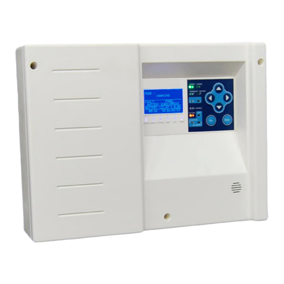
- Page 1 Installation guide for GR-6500 Addressable control panel for Emergency luminaires...
-
Page 2: Table Of Contents
Contents Operation instructions ......................... 3 1.1. Description ..........................3 1.2. Safety ............................3 1.3. Indications and Controls ......................3 1.4. General LCD indications ......................4 User Menu ............................6 2.1. Test menu ..........................7 2.2. Information menu ........................10 2.3. Events menu .......................... -
Page 3: Operation Instructions
1.1. Description The GR-6500 is a 16 zone addressable control panel for emergency luminaires that can connect with 250 devices. All the luminaires that are connected on the loop are displayed on the panel with the general term «POINTS». This term will be also used in the instructions below from now on. -
Page 4: General Lcd Indications
1.4. General LCD indications A typical main screen of the panel GR-6500 is shown below. Figure 1-2 The LCD is divided is four sections. The first section is the current mode of the panel. The modes can... - Page 5 • “CHARGING” all the luminaires are in charging mode • “EMERGENCY” at least one of the luminaires is in emergency mode • “FUNCTION TEST” a function test is running • “CAPACITY TEST” a capacity test is running • “INHIBIT” inhibit mode is active •...
-
Page 6: User Menu
2. User Menu By pressing “Enter” you have access to the user menu of the panel. There is a general diagram of the user menu options below. MENU CURRENT FAULTS SHOW FAULTS RESET FAULTS LUMINAIRES MODE INHIBIT OFF IN EMERGENCY TEST INFORMATION TECHNICIAN MENU... -
Page 7: Test Menu
Figure 2-6 The last line shows the index of the fault and the number of all faults. By pressing the “RESET FAULTS” the panel deletes and resets all faults. The next option “LUMINAIRES” sends commands to the luminaires connected to the panel. The option “MODE INHIBIT”... - Page 8 • To make a function test of all luminaires or a specific zone choose “MAKE A FUNCTION TEST” • “ZONE IN TEST” shows which zones are on a function or autonomy test • “POINTS IN TEST” shows which points are on a function or autonomy test •...
- Page 9 Figure 2-9 Press one last time the “RIGHT” key to see the last flag of the luminaire like, function test, capacity test, inhibit mode, if the battery is fully charged and the last autonomy in minutes. Figure 2-10 If you press “ENTER” you can send commands to this specific luminaire. The commands are shown at the next picture.
-
Page 10: Information Menu
2.2. Information menu In the information menu the options are: INFORMATION MENU PANEL LOOP LOOP OUPUT ZONES ZONES IN EMERGENCY ZONES IN FAULT DISABLED ZONES POINTS SHOW DISABLED NETWORK PANEL SOFT VERSION TECHNICIAN INFO Figure 2-12 • “PANEL” shows information about mains power supply, battery and the charger •... - Page 11 Figure 2-13 At the screen above you can see a typical event. The first line shows the type of the event FAULT, or GENERAL (information). The second line shows the source of the event for example PANEL, POINT 230 (point at address 230). The third line shows a description of the event, for example “NOT REGISTERED”...
-
Page 12: Installation Instructions
3. Installation instructions Connections between the control panel and the luminaire modules is consisted of a 2 core twisted pair cable. The figure below shows the interior of the panel and the keyboard. ° Please install the panel in a clean and dry environment with an ambient temperature of between 5 °... -
Page 13: Topology Of The Installation
Olympia Electronics recommends the following cables: 1. YSLY-OZ 2. LiYCY Typical cable cross section is from 0.75mm2 to 2.5mm2 depending on the number of connected luminaires, topology of the installation and length of cable runs. 3.2. Topology of the installation The maximum number of luminaires connected to the panel is 250. - Page 14 GR-421/3L/1/ADR GR-421/6L/1/ADR GR-423/3L/1/ADR GR-423/6L/1/ADR GR-421/3L/1/M/ADR GR-427/12L/ADR GR-736/21L/ADR GR-119/L/ADR GR-315/4P/ADR GR-315/6P/ADR GR-316/6P/ADR GR-316/4P/ADR GR-315/15L/ADR GR-315/30L/ADR GR-316/15L/ADR GR-316/30L/ADR GR-938/4P/ADR GR-938/6P/ADR GR-939/4P/ADR GR-939/6P/ADR GR-938/15L/ADR GR-938/30L/ADR GR-939/15L/ADR GR-939/30L/ADR GR-576/L/ADR GR-1009/24L/ADR SLD-28/ADR SLD-34/ADR SLD-44/ADR SLD-64/ADR ZLD-28/ADR ZLD-34/ADR ZLD-44/ADR GR-638/ADR GR-639/ADR GR-312/6P/ADR GR-312/4P/ADR GR-312/30L/ADR GR-312/15L/ADR GR-310/6P/ADR GR-310/4P/ADR GR-310/30L/ADR GR-310/15L/ADR...
-
Page 15: Cross Cable Selection
250 mA. The total loop current of the installation is calculated by adding the total current consumption of each device in normal operation. If in any condition we exceed the current limit of 250mA, we must install a second GR-6500 panel to create a network. The devices will be divided into two panels. -
Page 16: Useful Information For Panel Installation
3.6. Network connection The GR-6500 panel can be connected to a Local Area Network via Ethernet and can be accessed remotely via a PC and a common web browser. The Ethernet network connectivity, is provided by the GR-8530 Ethernet card (10BASE-T controller) (optional accessory - contact your sales representative). -
Page 17: Relay Operation
At the right bottom corner of the panel PCB there is a mini USB-B connector. This USB is used for communication between the panel and the software PC GR-6500. You can update the firmware of the panel by using the software too. - Page 18 Please follow the general guidelines bellow for any installation: • External cables must be connected using the cable entries or knockouts provided. • When routing external cables inside the panel they must be kept as short as possible • Cables must be routed close to the housing •...
-
Page 19: Technician Menu
4. Technician menu To enter the technician menu you must press “Enter” from the main screen, then select the option “TECHNICIAN MENU”. Then you must enter the technician code. The default code is 1000. You can see a figure of the enter code screen below. With Up-Down keys you change the digit, Right-Left keys you move to the next digit. -
Page 20: Menu Settings
• “SYSTEM” where you can automatically setup (register) all points of the loop • “POINTS” configure each point of the panel • “SETTINGS” configure parameters of the panel. See paragraph 4.1. • “ENABLE” a point, a zone, all zones. • “DISABLE”... -
Page 21: Function Test Menu
• “TIME SETTING” set the time of the panel • “SELECT LANGUAGE” choose language between GREEK and ENGLISH • “BUZZER SETTINGS” set buzzer on/off • “ANNUAL CHECK WARNING” enable/disable the annual check warning • “MENU MANUFACTURER” you need the code of the manufacturer to access this menu 4.2. -
Page 22: Ethernet Menu
MAKE A CAPACITY TEST MAKE CAPACITY TEST ALL ZONES ONE ZONE ONLY STOP CAPACITY TEST ALL ZONES ONE ZONE ONLY Figure 4-18 It is also possible to stop a capacity test from the same menu (see figure above). 4.4. Ethernet menu At the Ethernet menu you can set the Ethernet parameters ETHERNET ETHERNET PCB... -
Page 23: Pc - Visualising Via Web Browser
5. PC - Visualising via web browser You can monitor and control the panel from any device (pc, mobile etc) and from any OS with the use of an internet browser. No special software is necessary. A connection of the system with the local network via standard network cable with RJ45 interface is required. -
Page 24: Technical Characteristics - Specifications
6. Technical Characteristics – Specifications Description GR-6500 1 loop 16 zone adressable luminaire panel Power Supply 220-240VAC/50-60HZ Consumption 25W (0.150A AC) Battery type Sealed lead acid (Pb) battery 12V / 7Ah Max Charger Stabilized power supply 13,8V / 400mA Loop circuit The maximum number of addressable modules connected to the panel is 250.
Need help?
Do you have a question about the GR-6500 and is the answer not in the manual?
Questions and answers