Table of Contents
Advertisement
CORPORATE OFFICE
JLG INDUSTRIES, INC.
1 JLG Drive
McConnellsburg, PA 17233-9533
USA
Telephone: (717) 485-5161
Fax: (717) 485-6417
EUROPEAN OFFICE
JLG INDUSTRIES (EUROPE)
Kilmartin Place,
Tannochside Park,
Uddingston, Scotland, G71 5PH
Telephone: 01698 811005
Fax: 01698 811055
AUSTRALIAN OFFICE
JLG INDUSTRIES (AUSTRALIA)
P.0. Box 972
11 Bolwarra Road
Port MacQuarie
N.S.W. 44
Australia
Telephone: 1 (065) 811111
Fax: 1 (065) 810122
B S E N I S O 90 01 C er tificat e N o. 6 917
Models
M45A
M45AJ
E45A
E45AJ
Issued: April 1, 1999
Updated: March 15, 2000
PRINTED IN U.S.A.
3120883
Advertisement
Table of Contents

Related Manuals for JLG E45A


Summarization of Contents
FOREWORD
Safety Alert Symbol Definitions
Defines safety alert symbols and their meanings for potential hazards.
OSHA Regulations Overview
Summarizes key OSHA safety regulations for aerial lift operation.
SECTION 1 - SAFETY PRECAUTIONS
1.1 GENERAL
Outlines safe practices, manual importance, and operator responsibility for machine usage.
1.2 DRIVING/TOWING
Provides guidance on driving safely and notes the machine's towing provisions.
1.3 ELECTROCUTION HAZARD
Details minimum safe approach distances to electrical conductors and hazards.
1.4 PRE-OPERATIONAL
Emphasizes manual reading, understanding, and use by authorized, qualified personnel.
Operator Responsibilities
Highlights operator's duty for training, work area safety, and machine maintenance.
Operational Restrictions
Lists restrictions on operation, including wind limits, modifications, and temperature ranges.
Safe Operation Practices
Details safe practices like reading manuals, using ground controls, and maintaining three-point contact.
Driving Safety
Provides safety guidelines for driving, including speed, grades, obstructions, and personnel proximity.
Operation Safety
Covers safe operation, checking travel paths, grades, surfaces, and platform entry/exit.
Platform Safety
Emphasizes fall protection device use and safe procedures for entering/leaving the platform.
Transfer Safety
Details safety measures for transfers between structures and the platform, including lanyard use.
General Operation Precautions
Lists precautions for platform items, footing, cleanliness, and avoiding boom walking.
Load Limits and Malfunctions
Addresses load limits, handling malfunctions, footswitch, stuck machines, and prohibited boom uses.
1.7 TOWING AND HAULING
Details procedures for towing and hauling, including turntable locking.
SECTION 2 - PREPARATION AND INSPECTION
2.1 GENERAL
Stresses the importance of read/understood information and the owner/operator's responsibility for safety.
2.2 PREPARATION FOR USE
Covers initial inspection of new machines and periodic checks for operational readiness.
2.3 DELIVERY AND FREQUENT INSPECTION
Outlines requirements for periodic safety and maintenance inspections by an authorized dealer.
Chassis Inspection Points
Details specific inspection points for the machine's chassis, including tires, axles, and steering.
Turntable Inspection Points
Lists inspection points for the turntable, including cylinders, drive motor, and bearing.
Boom Inspection Points
Details inspection points for the boom, including pins, hydraulic lines, and cylinders.
Platform Inspection Points
Lists inspection points for the platform, including console, controls, and wiring.
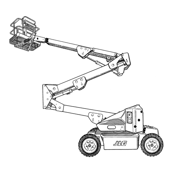
Basic Nomenclature
Illustrates and labels the major components of the JLG Lift machine.
2.4 DAILY WALK-AROUND INSPECTION
Details the operator's daily inspection routine, including cleanliness, placards, and manuals.
2.5 DAILY FUNCTIONAL CHECK
Outlines the process for performing a daily functional check of all machine systems.
Functional Checks - Boom and Controls
Describes specific functional checks for boom movements, controls, and the footswitch.
2.6 TORQUE REQUIREMENTS
Explains the purpose of the torque chart for bolt tightening and maintenance.
Lubrication Chart
Illustrates lubrication points on the machine with corresponding numbers.
Table 2-1. Lubrication Chart
Provides a detailed chart of components, lube points, capacity, intervals, and lubricant types.
Figure 2-4. Torque Chart
Displays standard torque values for various bolt sizes and grades for proper fastener tightening.
Battery Maintenance and Charging
Details procedures for battery maintenance, including cleaning and electrolyte checks.
SECTION 3 - USER RESPONSIBILITIES AND MACHINE CONTROL
3.1 GENERAL
Emphasizes the user's responsibility for machine application, operation, and safety.
3.2 PERSONNEL TRAINING
Stresses the necessity of operating and maintaining the machine by authorized, qualified, and trained personnel.
3.3 OPERATING CHARACTERISTICS AND LIMITATIONS
Covers machine characteristics, limitations, placards, capacities, and stability factors.
3.4 CONTROLS AND INDICATORS
Introduces control panels, symbols, and ground control station functions.
Position of Least Forward Stability
Illustrates the machine's configuration for least forward stability, highlighting tip-over risk.
Position of Least Backward Stability
Illustrates the machine's configuration for least backward stability, highlighting tip-over risk.
Ground Control Station Diagram
Displays the layout and labels of the ground control station components.
Ground Control Station Functions
Explains the operation and functions of the ground control station switches and controls.
Platform Console Layout
Displays the layout and labels of the platform control console components.
Platform Control Functions
Explains the operation and functions of platform controls, including joystick and footswitch.
Simultaneous Functions Table
Details which machine functions can be operated simultaneously and their interactions.
Decal Location Guide
Illustrates the locations of various safety decals (Danger, Caution, Warning, Important) on the machine.
Safety Decals and Daily Checklist
Presents safety warnings and a daily inspection checklist with operational limits.
Generator Operation Warnings
Provides critical warnings and instructions for safe operation of the onboard generator.
Control Panel Symbols - Part 1
Shows and explains the symbols used for various functions on the control panels.
Control Panel Symbols - Part 2
Continues the explanation of control panel symbols for machine functions.
SECTION 4 - MACHINE OPERATION
4.1 DESCRIPTION
Describes the JLG Lift as a self-propelled hydraulic lift with a work platform and boom.
4.2 GENERAL
Highlights the importance of understanding operating procedures for traveling, steering, and parking.
4.3 MOTOR OPERATION
Explains the function of the Power/Emergency Stop switch and its role in machine operation.
Platform/Ground Select & Motor Activation
Explains how motors are activated, emphasizing the footswitch requirement and safety warnings.
Traveling (Driving) Procedures
Provides notes and warnings related to driving the machine, including speed and conditions.
Steering
Explains how to steer the machine using the thumb switch on the controller.
Platform Loading and Adjustment
Covers platform loading from ground level and platform level adjustment procedures.
Platform Rotation
Details the procedure for rotating the platform to the left or right.
Boom Operation
Provides warnings related to boom operation, including tilt and slope hazards.
Generator Operation
Describes the machine's generator and its automatic and battery-only operating modes.
Machine Function Speeds
Describes the Function Speed Control and its effect on boom and swing speeds.
Shut Down and Park
Outlines the correct procedures for shutting down and parking the machine.
Machine Lifting and Tie Down
Provides instructions for lifting and tie-down procedures for the machine.
Boom Synchronizing Procedure
Details the procedure to synchronize the boom assembly if it does not fully lower.
Upright Positioning Guidelines
Illustrates correct and incorrect upright positioning to prevent tip-over hazards.
Lifting Chart
Provides lifting instructions and a chart with dimensions and weights for different models.
Chassis and Platform Tie Down
Illustrates how to properly secure the chassis and platform for transport.
SECTION 5 - OPTIONAL EQUIPMENT
Motion Alarm
Describes the audible warning provided by the motion alarm.
Foam Filled Tires
Explains the benefit of foam-filled tires for use in challenging jobsite conditions.
Rotating Beacon
Details the function of the amber rotating beacon as a visual warning.
Tilt Alarm
Describes the audible warning that sounds when the machine is out of level.
Wheel Covers
Explains the protective function of wheel covers against dirt and debris.
Battery Packs
Notes the availability of spare battery packs for continuous operation.
Platform Lights
Mentions the availability of platform lights for improved operator visibility.
Control Console Cover
Describes the clear acrylic cover protecting the platform control console.
Cylinder Bellows
Explains the purpose of cylinder bellows in protecting cylinder rods.
Work Platform
States the available size for the work platform.
SECTION 6 - EMERGENCY PROCEDURES
6.1 GENERAL
Stresses reviewing emergency procedures for all personnel interacting with the machine.
6.2 EMERGENCY TOWING PROCEDURES
Provides procedures for moving the machine in emergency situations, like malfunctions.
6.3 EMERGENCY CONTROLS AND THEIR LOCATIONS
Details the location and function of the Emergency Stop switch.
Ground Control Station
Identifies the location of the Ground Control Station and its overriding capabilities.
Manual Descent System
Explains how to use the manual descent system to lower booms in case of power failure.
Manual Swing Override
Details how to manually swing the boom/turntable assembly in an emergency.
6.4 EMERGENCY OPERATION
Outlines the use of ground controls during emergencies and training requirements.
Operator Unable to Control Machine
Provides instructions for handling situations where the platform operator is incapacitated.
Platform or Boom Caught Overhead
Details procedures if the platform or boom becomes jammed overhead.
6.5 INCIDENT NOTIFICATION
Stresses the importance of immediate notification to JLG Industries regarding any incidents.
SECTION 7 - INSPECTION AND REPAIR LOG
Table 7-1. Inspection and Repair Log
Provides a template for recording inspection and repair details.
Need help?
Do you have a question about the E45A and is the answer not in the manual?
Questions and answers