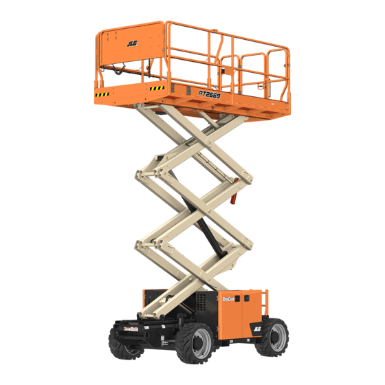
JLG RT2669 Operation And Safety Manual
Hide thumbs
Also See for RT2669:
- Service and maintenance manual (376 pages) ,
- Operation & safety manual (128 pages)

Related Manuals for JLG RT2669


Summary of Contents for JLG RT2669
- Page 1 Operation and Safety Manual Original Instructions - Keep this manual with the machine at all times. Models RT2669, RT3369 ERT2669, ERT3369 PVC 2004 ANSI AS/NZS 31217162 ® September 28, 2021 - Rev B...
- Page 2 WARNING Operating, servicing and maintaining this vehicle or equipment can expose you to chemicals including engine exhaust, carbon monoxide, phthalates, and lead, which are known to the State of California to cause cancer and birth defects or other reproductive harm. To minimize exposure, avoid breathing exhaust, do not idle the engine except as necessary, service your vehicle or equipment in a well-ventilated area and wear gloves or wash your hands frequently when servicing.
- Page 3 The purpose of this manual is to provide owners, users, operators, lessors, and lessees with the precautions and operating procedures essential for the safe and proper machine operation for its intended purpose. Due to continuous product improvements, JLG Industries, Inc. reserves the right to make specification changes without prior notification. Contact JLG Industries, Inc. for updated information.
- Page 4 FOREWORD SAFETY ALERT SYMBOLS AND SAFETY SIGNAL WORDS THIS IS THE SAFETY ALERT SYMBOL. IT IS USED TO ALERT YOU TO THE POTENTIAL PERSONAL INJURY HAZARDS. OBEY ALL SAFETY MESSAGES THAT FOLLOW THIS SYMBOL TO AVOID POSSIBLE INJURY OR DEATH. INDICATES A POTENTIALLY HAZARDOUS SITUATION.
- Page 5 Modifications Product Safety JLG INDUSTRIES, INC. SENDS SAFETY RELATED BULLETINS TO THE OWNER OF RECORD OF THIS MACHINE. CONTACT JLG INDUSTRIES, INC. TO ENSURE THAT THE Contact: CURRENT OWNER RECORDS ARE UPDATED AND ACCURATE. Product Safety and Reliability Department JLG Industries, Inc.
- Page 6 FOREWORD REVISION LOG Original Issue A - October 20, 2020 Revised B - September 28, 2021 31217162...
-
Page 7: Table Of Contents
TABLE OF CONTENTS SECTION - 1 - SAFETY PRECAUTIONS PRE-START INSPECTION ......2-4 WALK-AROUND INSPECTION . - Page 8 Starting Procedure ....... 3-25 RT2669, RT3369 ........3-42 Dual Fuel System (If Equipped).
- Page 9 TABLE OF CONTENTS SECTION - 5 - ACCESSORIES OPERATOR MAINTENANCE AND LUBRICATION ..6-16 General Maintenance Tips ..... . . 6-16 AVAILABLE ACCESSORIES .
- Page 10 TABLE OF CONTENTS SECTION - 7 - INSPECTION AND REPAIR LOG LIST OF TABLES Minimum Approach Distances (M.A.D.) ..... . 1-6 Beaufort Scale (For Reference Only).
-
Page 11: Section 1. Safety Precautions
• Only personnel who have received proper training regarding nance, application, and operation, please contact JLG Industries, the inspection, application, and operation of MEWPs (includ- Inc. (“JLG”). -
Page 12: Workplace Inspection
WRITTEN PERMISSION FROM THE MANUFACTURER trailers, railway cars, floating vessels, scaffolds or other equip- ment unless the application is approved in writing by JLG. • Do not operate any machine on which the safety or instruction placards or decals are missing or illegible. -
Page 13: Operation
SECTION 1 - SAFETY PRECAUTIONS OPERATION • Do not carry materials directly on platform railing unless approved by JLG. General • When two or more persons are in the platform, the operator shall be responsible for all machine operations. • Machine operation requires your full attention. Bring the •... -
Page 14: Trip And Fall Hazards
• Prior to operation, ensure all gates and rails are fastened and secured in their proper position. • JLG Industries, Inc. recommends that all persons in the plat- form wear a full body harness with a lanyard attached to an authorized lanyard anchorage point while operating this •... -
Page 15: Electrocution Hazards
SECTION 1 - SAFETY PRECAUTIONS Electrocution Hazards • This machine is not insulated and does not provide protection from contact or proximity to electrical current. • Maintain safe clearance from electrical lines, apparatus, or any energized (exposed or insulated) parts in accordance with the Minimum Approach Distance (MAD) as specified in Table 1-1. -
Page 16: Tipping Hazards
Keep all loads within the confines of the plat- (Phase to Phase) in Feet (Meters) form, unless authorized by JLG. 0 to 50KV 10 (3) • Keep the chassis of the machine a minimum of 0.6 m (2 ft) - Page 17 SECTION 1 - SAFETY PRECAUTIONS DO NOT OPERATE THE MACHINE WHEN WIND CONDITIONS EXCEED SPECIFICATIONS SHOWN IN SECTION 6.3 OR AS SHOWN ON THE CAPACITY PLACARD ON THE PLAT- FORM BILLBOARD. Table 1-2. Beaufort Scale (For Reference Only) Wind Speed Beaufort Description Land Conditions...
- Page 18 SECTION 1 - SAFETY PRECAUTIONS • Never attempt to use the machine as a crane. Do not tie-off machine to any adjacent structure. Never attach wire, cable, or any similar items to platform. • If scissor arm assembly or platform is caught so that one or more wheels are off the ground, all persons must be removed before attempting to free the machine.
-
Page 19: Crushing And Collision Hazards
SECTION 1 - SAFETY PRECAUTIONS Crushing and Collision Hazards • Keep non-operating personnel at least 6 ft (1.8 m) away from machine during all driving operations. • Approved head gear must be worn by all operating and • Under all travel conditions, the operator must limit travel ground personnel. -
Page 20: Towing, Lifting, And Hauling
SECTION 1 - SAFETY PRECAUTIONS TOWING, LIFTING, AND HAULING MAINTENANCE General • Never allow personnel in platform while towing, lifting, or hauling. This section contains general safety precautions which must be • This machine should not be towed, except in the event of observed during maintenance of this machine. -
Page 21: Battery Hazards
• Use only replacement parts or com- batteries. Ensure that battery acid does not come in contact ponents that are approved by JLG. To be considered approved, with skin or clothing. replacement parts or components must be identical or equiva- lent to original parts or components •... - Page 22 SECTION 1 - SAFETY PRECAUTIONS 1-12 31217162...
-
Page 23: Section 2 - User Responsibilities, Machine Preparation, And Inspection
SECTION 2 - USER RESPONSIBILITIES, MACHINE PREPARATION, AND INSPECTION SECTION 2. USER RESPONSIBILITIES, MACHINE PREPARATION, AND INSPECTION PERSONNEL TRAINING Means to avoid the hazards of unprotected electrical con- ductors. The Mobile Elevating Work Platform (MEWP) is a personnel han- Selection of the appropriate MEWPs and available options dling device, so it is necessary that it be operated and maintained for the work to be performed considering specific job requirements, with involvement from the MEWP owner, user,... -
Page 24: Machine Familiarization
Responsibilities for familiarization may vary by region. The following table covers the machine inspections and mainte- nance recommended by JLG Industries, Inc. Consult local regula- Only properly trained personnel who have received unit-specific tions for further requirements for MEWPs. The frequency of familiarization shall operate a MEWP. -
Page 25: Inspection And Maintenance Table
Inspection forms are available from JLG. Use the Service and Maintenance Manual to perform inspections. NOTICE JLG INDUSTRIES, INC. RECOGNIZES A FACTORY-TRAINED SERVICE TECHNICIAN AS A PERSON WHO HAS SUCCESSFULLY COMPLETED THE JLG SERVICE TRAINING SCHOOL FOR THE SPECIFIC JLG PRODUCT MODEL. -
Page 26: Pre-Start Inspection
Make sure all illegible decals and placards are cleaned or replaced. Lanyard Anchorage Points – JLG Industries, Inc. recom- mends personnel in the platform wear a full body harness Operation and Safety Manuals – Ensure a copy of the... - Page 27 SECTION 2 - USER RESPONSIBILITIES, MACHINE PREPARATION, AND INSPECTION OAD02640 Lanyard Attach Points OAD02340 Platform Gate 31217162...
-
Page 28: Walk-Around Inspection
SECTION 2 - USER RESPONSIBILITIES, MACHINE PREPARATION, AND INSPECTION WALK-AROUND INSPECTION OAD02310 RT2669, RT3669 31217162... - Page 29 SECTION 2 - USER RESPONSIBILITIES, MACHINE PREPARATION, AND INSPECTION OAD02320 ERT2669, ERT3669 31217162...
- Page 30 SECTION 2 - USER RESPONSIBILITIES, MACHINE PREPARATION, AND INSPECTION Begin the Walk-Around Inspection at Item 1, as noted on the dia- Fuel Tank (Diesel or Gasoline) (If Equipped) - Filler cap secure, no damage or leaks. gram. Continue to the right (counterclockwise viewed from top) checking each item in sequence for the conditions listed in the Hydraulic Tank - Recommended hydraulic fluid level on following checklist.
- Page 31 SECTION 2 - USER RESPONSIBILITIES, MACHINE PREPARATION, AND INSPECTION Safety Prop - Refer to Inspection Note. Scissor Arms and Wear Pads - Refer to Inspection Note. Manual Descent - Refer to Inspection Note. Lift Cylinder - Refer to Inspection Note. QuikLevel Advanced (Dual Oscillating Axles) (If Platform Controls - Properly secured, no loose or missing Equipped) - Refer to Inspection Note.
-
Page 32: Function Check
Ensure all guards protecting switches are in place. b. Operate all functions (refer to Section 3.6 for Ground Model Height Controls and Indicators). RT2669, ERT2669 70 in (1.78 m) c. Ensure that all machine functions are disabled when the Emergency Stop Button is activated. RT3369, ERT3369 80 in (2.03 m) - Page 33 Side to beyond the following limits: Side beyond the following limits: 4.0° at 0% - 55% Capacity RT2669, ERT2669 3° 3.0° at 56% - 75% Capacity 2.5° at 76% - 100% Capacity 3.5° at 0% - 35% Capacity RT3369, ERT3369 3°...
-
Page 34: Oscillating Axle - Lockout Cylinder Test (If Equipped)
SECTION 2 - USER RESPONSIBILITIES, MACHINE PREPARATION, AND INSPECTION OSCILLATING AXLE - LOCKOUT CYLINDER TEST (IF 4. Verify the axle oscillates to maintain contact with the ground/ ramp. (All four wheels on the ground.) EQUIPPED) 5. Raise machine platform above stowed position to drive cutout height. - Page 35 SECTION 2 - USER RESPONSIBILITIES, MACHINE PREPARATION, AND INSPECTION Right Side Wheel Test 8. In the current position (platform raised and all four tires on flat and level surface), carefully drive machine up the ramp block again. 1. Place a 4 in (10.16 cm) high block with ascension ramp in front of right wheel of the oscillating axle.
-
Page 36: All Markets (Except Ce)
SECTION 2 - USER RESPONSIBILITIES, MACHINE PREPARATION, AND INSPECTION All Markets (Except CE) 8. Return the machine to the stowed position. The lockout cylin- der should release and allow wheel to rest on the ground. It may be necessary to activate DRIVE to release cylinder. 9. -
Page 37: Section 3. Machine Controls, Indicators, And Machine Operation
SECTION 3 - MACHINE CONTROLS, INDICATORS, AND MACHINE OPERATION SECTION 3. MACHINE CONTROLS, INDICATORS, AND MACHINE OPERATION GENERAL DESCRIPTION This machine is a Mobile Elevating Work Platform (MEWP) used to position personnel along with their necessary tools and materials THE MANUFACTURER HAS NO DIRECT CONTROL OVER MACHINE APPLICATION AND at work locations. -
Page 38: Operating Characteristics And Limitations
Load is within manufacturer’s rated capacity. All machine systems are functioning properly. Stability This machine, as originally manufactured by JLG and operated within its rated capacity on a smooth, firm surface, within the lim- its of the maximum operating slope, provides a stable aerial plat- form for all platform positions. -
Page 39: Battery Charging (Ert Machines)
SECTION 3 - MACHINE CONTROLS, INDICATORS, AND MACHINE OPERATION BATTERY CHARGING (ERT MACHINES) Connect the charger AC input plug to a grounded outlet using a 3 wire heavy duty extension cord. The charge cycle is complete when the single green LED light on the hood between the AC plug and battery discon- nect becomes solid green. - Page 40 SECTION 3 - MACHINE CONTROLS, INDICATORS, AND MACHINE OPERATION OAD02470 3. LED Indicator Panel OAD02810 • AC Power On: Blue LED on • (1) Charging (Low State of Charge): Green LED slow flash • Low State of Charge: Bottom Panel - Green LED flashing; •...
-
Page 41: Ground Control Station
SECTION 3 - MACHINE CONTROLS, INDICATORS, AND MACHINE OPERATION GROUND CONTROL STATION RT Machines Emergency Stop Switch Overload Indicator (LSS) Lift/Lower Switch Display Gauge Engine Start Switch Ground/Platform/OFF Key Selector Switch OAD02030 31217162... -
Page 42: Ert Machines
SECTION 3 - MACHINE CONTROLS, INDICATORS, AND MACHINE OPERATION ERT Machines Emergency Stop Switch Overload Indicator (LSS) Lift/Lower Switch Display Gauge Not Used Ground/Platform/OFF Key Selector Switch Genset Start Switch (If Equipped) Genset Indicator (If Equipped) OAD02050 31217162... -
Page 43: Ground Controls
SECTION 3 - MACHINE CONTROLS, INDICATORS, AND MACHINE OPERATION Ground Controls Overload Indicator (LSS) - The Overload Indicator indicates when the platform has been overloaded. An audible alarm will also signal when the platform is overloaded. NOTE: If the Overload Indicator is illuminated, further elevation will be DO NOT OPERATE FROM GROUND CONTROL STATION WITH PERSONNEL IN THE PLAT- prevented. - Page 44 SECTION 3 - MACHINE CONTROLS, INDICATORS, AND MACHINE OPERATION Engine Start Switch (RT Machines Only) - A momentary Genset Start Switch (If Equipped) - This button activates the genset system to charge the batteries. contact push button type switch that supplies electrical power to the starter solenoid when the emergency stop Genset Indicator (If Equipped) - This will illuminate when a switch is in the ON position and the start button is pressed.
-
Page 45: Display Gauge
SECTION 3 - MACHINE CONTROLS, INDICATORS, AND MACHINE OPERATION Display Gauge 1. Battery Temperature Indicator 2. Navigate Back Arrow 3. Charger Connected Indicator (ERT Machines Only) 4. Machine Hours 5. Indicator Lamp (Fault) 6. Fuel Level Indicator (RT Machines Only) 7. - Page 46 The Diagnostic Screen will show active and inactive faults from machine start up, with no active DTCs in the control system, the the JLG Control System on the screen. An asterisk (*) will be dis- splash screen will show for 3 seconds and then switch to main played to show active faults.
-
Page 47: Platform Control Station
SECTION 3 - MACHINE CONTROLS, INDICATORS, AND MACHINE OPERATION PLATFORM CONTROL STATION RT Machines Emergency Stop Switch Lift Select Switch Drive Select Switch Engine Start Switch Horn Speed Select Switch Leveling Jacks OR QuikLevel Advanced Switch Mobile Phone Slot Dual Fuel Selection (If Equipped) Generator Start Switch (If Equipped) USB Charge Port Indicator Display... -
Page 48: Ert Machines
SECTION 3 - MACHINE CONTROLS, INDICATORS, AND MACHINE OPERATION ERT Machines Emergency Stop Switch Lift Select Switch Drive Select Switch Not Used Horn Speed Select Switch Leveling Jacks Switch (If Equipped) Mobile Phone Slot Not Used Not Used USB Charge Port Indicator Display Steer Control Switch Joystick Controller with Trigger... -
Page 49: Platform Controls
SECTION 3 - MACHINE CONTROLS, INDICATORS, AND MACHINE OPERATION NOTE: When diesel engine-powered machines are turned on, the glow Platform Controls plug indicator will illuminate on the platform control indicator display, regardless of engine or ambient temperature. Do not Emergency Stop Switch - A two-position, red, mushroom- start the engine until the glow plug indicator light disappears. - Page 50 SECTION 3 - MACHINE CONTROLS, INDICATORS, AND MACHINE OPERATION Steer Control Switch - The thumb-operated steer switch on top of the joystick controller activates the steer wheels in the DO NOT USE HIGH DRIVE SPEED WHEN DRIVING IN CLOSE QUARTERS OR WHEN DRIV- direction it is moved (right or left).
-
Page 51: Indicator Display
SECTION 3 - MACHINE CONTROLS, INDICATORS, AND MACHINE OPERATION INDICATOR DISPLAY RT Machines (If Equipped with Leveling Jacks) 1. Lift Sense Pane 2. Side to Side Tilt 3. Front to Back Tilt 4. Platform Load Gauge 5. Current Platform Height 6. -
Page 52: Rt Machines
SECTION 3 - MACHINE CONTROLS, INDICATORS, AND MACHINE OPERATION RT Machines (If Equipped with QuikLevel Advanced) 1. Lift Sense Pane 2. Side to Side Tilt 3. Front to Back Tilt 4. Platform Load Gauge 5. Current Platform Height 6. Not Used 7. -
Page 53: Ert Machines (If Equipped With Leveling Jacks)
SECTION 3 - MACHINE CONTROLS, INDICATORS, AND MACHINE OPERATION ERT Machines (If Equipped with Leveling Jacks) 1. Lift Sense Pane 2. Side to Side Tilt 3. Front to Back Tilt 4. Platform Load Gauge 5. Current Platform Height 6. Leveling Jacks Indicator (If Equipped) 7. -
Page 54: Indicators
SECTION 3 - MACHINE CONTROLS, INDICATORS, AND MACHINE OPERATION Indicators The LiftSense pane can be hidden by pressing the far left button of the display. Press this button again to return the pane to view. IF THE TILT INDICATOR WARNING LIGHT/ALARM IS ACTIVATED WHEN PLATFORM IS RAISED, LOWER PLATFORM AND DRIVE TO A SMOOTH, FIRM SURFACE WITHIN THE LIMITS OF THE MAXIMUM OPERATING SLOPE. - Page 55 SECTION 3 - MACHINE CONTROLS, INDICATORS, AND MACHINE OPERATION Side to Side Tilt - Shows the current level of Current Height - Current platform height (bot- tom number). side to side tilt. A red warning light on the display illuminates and an audible alarm sounds when the chassis is at or beyond the tilt cutout settings.
- Page 56 SECTION 3 - MACHINE CONTROLS, INDICATORS, AND MACHINE OPERATION Leveling Jack Status (If Equipped) - Dis- Drive Select Indicator - Indicates if drive plays the current status of leveling jacks. mode has been selected on the platform When the leveling jacks are extended or control console.
- Page 57 SECTION 3 - MACHINE CONTROLS, INDICATORS, AND MACHINE OPERATION Drive Speed - Maximum Allowed Platform Height - Maxi- mum allowed platform height as calculated by • RT Machines: Indicates whether LiftSense system. The number is green when high drive speed (rabbit), low maximum platform height can be reached.
-
Page 58: Platform Control Indicator Display
SECTION 3 - MACHINE CONTROLS, INDICATORS, AND MACHINE OPERATION QuikLevel Advanced Status (If Equipped) - Glow Plug (Not Shown) - When diesel engine-powered machines are turned on, • Rear Axle Extend: the glow plug indicator will illuminate on the display, regardless of engine or ambient temperature. - Page 59 SECTION 3 - MACHINE CONTROLS, INDICATORS, AND MACHINE OPERATION Use the Scroll Page Left and Scroll Page Right buttons (6) to cycle through the different pages of the menu selection. To view the submenus, press the Menu Select button (1). The page icon (7) will inform what page is currently being Use the Left and Right Navigation buttons (3) to move viewed.
-
Page 60: Submenus
SECTION 3 - MACHINE CONTROLS, INDICATORS, AND MACHINE OPERATION NOTE: When navigating the submenus of the display screen, pressing Programming: Provides the interface for updating software. the joystick trigger will return the view to the operating screen. A service level access code is needed. Refer to Service and Maintenance manual for further information. -
Page 61: 3.10 Engine Operation
FAILS TO START AFTER SEVERAL ATTEMPTS, REFER TO ENGINE MANUAL. coolant temperature may occur. To start machine: Contact JLG Customer Service for operation under abnormal • At Ground Controls: Position emergency stop switch to conditions. on, press engine start switch, and hold until engine starts. -
Page 62: Dual Fuel System (If Equipped)
SECTION 3 - MACHINE CONTROLS, INDICATORS, AND MACHINE OPERATION Dual Fuel System (If Equipped) Changing from LPG to Gasoline: With the engine operating on LPG under a no load condi- tion, position the LPG/GAS SELECT switch at the platform station to the GAS SELECT position. IT IS POSSIBLE TO SWITCH FROM ONE FUEL SOURCE TO THE OTHER WITHOUT ALLOW- ING THE ENGINE TO STOP. -
Page 63: 3.11 Driving
SECTION 3 - MACHINE CONTROLS, INDICATORS, AND MACHINE OPERATION 3.11 DRIVING Driving Forward Place the power selector switch at the ground control sta- tion to platform. DO NOT DRIVE WITH PLATFORM RAISED EXCEPT ON A SMOOTH, FIRM AND LEVEL Position the emergency stop switch at the platform control SURFACE WITHIN THE LIMITS OF THE MAXIMUM OPERATING SLOPE, FREE OF station to the on position. -
Page 64: Driving In Reverse
SECTION 3 - MACHINE CONTROLS, INDICATORS, AND MACHINE OPERATION Driving in Reverse Traveling on a Grade If traveling at high speed up a grade and the incline exceeds 7° to Position the power selector switch at the ground control sta- 10°... -
Page 65: Grade And Sideslope
SECTION 3 - MACHINE CONTROLS, INDICATORS, AND MACHINE OPERATION Grade and Sideslope OAD02660 RT2669, ERT2669 31217162 3-29... - Page 66 SECTION 3 - MACHINE CONTROLS, INDICATORS, AND MACHINE OPERATION OAD02670 RT3369, ERT3369 3-30 31217162...
-
Page 67: 3.12 Platform
SECTION 3 - MACHINE CONTROLS, INDICATORS, AND MACHINE OPERATION 3.12 PLATFORM Lowering Raising ENSURE SCISSOR ARM AREA IS FREE OF PERSONNEL PRIOR TO LOWERING PLATFORM. DO NOT LOWER WITHOUT COMPLETELY RETRACTING THE PLATFORM EXTENSION. DO NOT RAISE PLATFORM EXCEPT ON A SMOOTH, FIRM, AND LEVEL SURFACE WITHIN THE LIMITS OF THE MAXIMUM OPERATING SLOPE, FREE OF OBSTRUCTIONS AND If operating from the ground controls, position the lift switch to HOLES. -
Page 68: Platform Extension
SECTION 3 - MACHINE CONTROLS, INDICATORS, AND MACHINE OPERATION 3.13 LEVELING JACKS (IF EQUIPPED) Platform Extension The machine is equipped with a mechanical extension deck, The machine may be equipped with auto-leveling jacks with a which adds 3 ft (0.9 m) to the front of the platform, giving the manual adjust feature. -
Page 69: Manual Level Adjustment (Trim)
SECTION 3 - MACHINE CONTROLS, INDICATORS, AND MACHINE OPERATION Manual Level Adjustment (Trim) NOTE: If a 2/5 flash code through the system fault light at the platform control station, the machine is unable to level. Reposition and try NOTE: There is an override feature on the leveling jack system that again. -
Page 70: Quiklevel Advanced (Dual Oscillating Axles)
SECTION 3 - MACHINE CONTROLS, INDICATORS, AND MACHINE OPERATION 3.14 QUIKLEVEL ADVANCED (DUAL OSCILLATING AXLES) Continue to hold the joystick forward until the leveling sequence ends and the platform alarm sounds three times (IF EQUIPPED) to indicate this is complete. To realign the chassis with the rear axle, press the function The machine may be quipped with QuikLevel Advanced, auo-lev- button, then move the joystick backwards. -
Page 71: Manual Level Adjustment (Trim)
SECTION 3 - MACHINE CONTROLS, INDICATORS, AND MACHINE OPERATION 3.15 PARKING AND STOWING Manual Level Adjustment (Trim) NOTE: There is an override feature on the QuikLevel Advanced system Park and stow the machine as follows: that allows the operator to adjust (trim) the level of the machine Drive the machine to a reasonably well-protected and well- to the left or right when the platform is completely lowered. -
Page 72: 3.16 Tie Down/Lifting
SECTION 3 - MACHINE CONTROLS, INDICATORS, AND MACHINE OPERATION 3.16 TIE DOWN/LIFTING Lifting The machine may be lifted using a spreader bar and four equal Tie Down length straps or chains capable of supporting the full gross weight of the machine (refer to section 6 for machine gross When transporting the machine, the platform extension must be weight). - Page 73 SECTION 3 - MACHINE CONTROLS, INDICATORS, AND MACHINE OPERATION OAD02390 Tie Down/Lifting Diagram 31217162 3-37...
-
Page 74: 3.17 Towing
SECTION 3 - MACHINE CONTROLS, INDICATORS, AND MACHINE OPERATION 3.17 TOWING Remove the platform control station from the rails and place on the platform floor. It is not recommended that this machine be towed except in the Lift up and pull out front platform rails to release from latch. event of an emergency, such as a machine malfunction or a total Fold in towards side rails. - Page 75 SECTION 3 - MACHINE CONTROLS, INDICATORS, AND MACHINE OPERATION ART_OAD02780 31217162 3-39...
- Page 76 SECTION 3 - MACHINE CONTROLS, INDICATORS, AND MACHINE OPERATION ART_OAD02790 3-40 31217162...
- Page 77 SECTION 3 - MACHINE CONTROLS, INDICATORS, AND MACHINE OPERATION ART_OAD02800 31217162 3-41...
-
Page 78: 3.19 Decals
SECTION 3 - MACHINE CONTROLS, INDICATORS, AND MACHINE OPERATION 3.19 DECALS RT2669, RT3369 China ANSI ANSI Export CE/AUS OAD02270 3-42 31217162... - Page 79 SECTION 3 - MACHINE CONTROLS, INDICATORS, AND MACHINE OPERATION OAD02260 31217162 3-43...
- Page 80 SECTION 3 - MACHINE CONTROLS, INDICATORS, AND MACHINE OPERATION OAD02280 3-44 31217162...
- Page 81 SECTION 3 - MACHINE CONTROLS, INDICATORS, AND MACHINE OPERATION China ANSI Export ANSI CE/AUS OAD02290 31217162 3-45...
- Page 82 SECTION 3 - MACHINE CONTROLS, INDICATORS, AND MACHINE OPERATION ANSI/ANSI Export/CSA English/Korean English/Chinese Spanish/Portuguese English/Spanish English/French CE/AUS Item (1001256764-C) (1001256765-C) (1001256766-C) (1001256767-C) (1001256768-C) (1001256769-C) (1001256770-C) 1 - 3 1703821 1001162112 1705194 1704702 1704694 1704687 1001211779 1001162114 1001211779 1705043 1705041 1705040 1705671 1001211777 1001215751...
- Page 83 SECTION 3 - MACHINE CONTROLS, INDICATORS, AND MACHINE OPERATION ANSI/ANSI Export/CSA English/Korean English/Chinese Spanish/Portuguese English/Spanish English/French CE/AUS Item (1001256764-C) (1001256765-C) (1001256766-C) (1001256767-C) (1001256768-C) (1001256769-C) (1001256770-C) 1704277 1704277 1704277 1704277 1704277 1704277 1704277 1704412 1704412 1704412 1704412 1704412 1704412 1704412 70046028 70046028 70046028 70046028...
-
Page 84: Ert2669, Ert3369
SECTION 3 - MACHINE CONTROLS, INDICATORS, AND MACHINE OPERATION ERT2669, ERT3369 OAD02360 3-48 31217162... - Page 85 SECTION 3 - MACHINE CONTROLS, INDICATORS, AND MACHINE OPERATION China ANSI ANSI Export CE/AUS OAD02370 31217162 3-49...
- Page 86 SECTION 3 - MACHINE CONTROLS, INDICATORS, AND MACHINE OPERATION 19 20 China ANSI Export OAD02380 CE/AUS ANSI 3-50 31217162...
- Page 87 SECTION 3 - MACHINE CONTROLS, INDICATORS, AND MACHINE OPERATION ANSI/ANSI Export/CSA English/Korean English/Chinese Spanish/Portuguese English/Spanish English/French Item (1001256771-C) (1001256772-C) (1001256773-C) (1001256774-C) (1001256775-C) (1001256776-C) (1001256777-C) (1001256778-C) 1 - 3 1703821 1001162112 1705194 1704702 1704694 1704687 1001211779 1001162114 1001211779 1705043 1705041 1705040 1705671 1705671 1001211777...
- Page 88 SECTION 3 - MACHINE CONTROLS, INDICATORS, AND MACHINE OPERATION ANSI/ANSI Export/CSA English/Korean English/Chinese Spanish/Portuguese English/Spanish English/French Item (1001256771-C) (1001256772-C) (1001256773-C) (1001256774-C) (1001256775-C) (1001256776-C) (1001256777-C) (1001256778-C) 1001265579 1001265579 1001265579 1001265579 1001265579 1001265579 1001265579 1001265579 1704277 1704277 1704277 1704277 1704277 1704277 1704277 1704277 1704412 1704412...
-
Page 89: Section 4 - Emergency Procedures
JLG Industries, Inc. must be notified immediately of any incident RT Machines involving a JLG product. Even if no injury or property damage is evident, JLG must be contacted by telephone and provided with Ensure the machine is in the stowed position. Chock wheels all necessary details. -
Page 90: Ert Machines
SECTION 4 - EMERGENCY PROCEDURES ERT Machines Ensure the machine is in the stowed position. Chock wheels securely. Connect machine to suitable towing equipment. Pull out the emergency stop switch and position the key- switch to ground mode. Look for the yellow button (1) inside the hydraulic compart- ment on the side of the ground control panel. -
Page 91: Emergency Operation
SECTION 4 - EMERGENCY PROCEDURES EMERGENCY OPERATION Platform Caught Overhead If the platform becomes jammed or snagged in overhead struc- Use of Ground Controls tures or equipment, do the following: Shut off the machine. Rescue all people in the platform before freeing the KNOW HOW TO USE THE GROUND CONTROLS IN AN EMERGENCY SITUATION. -
Page 92: Righting Of Tipped Machine
SECTION 4 - EMERGENCY PROCEDURES Righting of Tipped Machine Grasp the T-handle and slowly pull out to lower the scissor arms/platform. When the platform is lowered to the desired A forktruck of suitable capacity or equivalent equipment should level, release the T-handle. be placed under the elevated side of the chassis, with a crane or other suitable lifting equipment used to lift the platform while the chassis is lowered by the forklift or other equipment. -
Page 93: Section 5. Accessories
SECTION 5 - ACCESSORIES SECTION 5. ACCESSORIES AVAILABLE ACCESSORIES Market Accessory ANSI ANSI Korea China (USA Only) Footswitch Generator (2500W) 31217162... -
Page 94: Footswitch
SECTION 5 - ACCESSORIES FOOTSWITCH GENERATOR (2500W) The generator (2500W) supplies AC power from the engine com- partment to an AC receptacle in the platform. All power regulation components are located in a watertight box connected by cable to the generator. The generator is activated by a switch on the platform control box. -
Page 95: Preparation And Inspection
SECTION 5 - ACCESSORIES Preparation and Inspection • Ensure generator is secure. • Check condition of belt and wiring. Operation Start the engine, then turn on the generator. 31217162... - Page 96 SECTION 5 - ACCESSORIES 31217162...
-
Page 97: Section 6 - General Specifications And Operator Maintenance
Other Publications Available Specific to this Machine: Annex III, Part B, Method 1 and 0 of the directive, is 106 dB (RT2669 and RT3369 only). Service and Maintenance Manual........31217913 The vibration total value to which the hand-arm system is sub- Illustrated Parts Manual ............ -
Page 98: Ec Declaration Of Conformity
Polaris avenue 63, • EN ISO 12100:2010 2132 JH Hoofddorp The Netherlands JLG Industries Inc. hereby declares that the above mentioned machine conforms with the requirements of: Contact / Position: • 2006/42/EC - Machinery Directive Senior Manager - Product Safety & Reliability •... -
Page 99: Machine Specifications
SECTION 6 - GENERAL SPECIFICATIONS AND OPERATOR MAINTENANCE MACHINE SPECIFICATIONS Operating Specifications Model Specification RT2669 ERT2669 RT3369 ERT3369 Maximum Platform Height 26 ft (8 m) 26 ft (8 m) 33 ft (10 m) 33 ft (10 m) Gross Machine Weight... - Page 100 SECTION 6 - GENERAL SPECIFICATIONS AND OPERATOR MAINTENANCE High Drive Speed Cutout Height 70 in (1.78 m) 70 in (1.78 m) 80 in (2.03 m) 80 in (2.03 m) Platform Lift Up Time (Rated Load) 24 - 32 sec 29 - 37 sec 32 - 40 sec 36 - 44 sec Platform Lift Down Time (Rated Load)
-
Page 101: Dimensions
Lift Up and Drive prevented Stowed Height when elevated and tilted Front when elevated and tilted Side to Model RT2669, ERT2669 96.7 in (2456 mm) to Back beyond the following Side beyond the following RT3369, ERT3369 102.91 in (2614 mm) -
Page 102: Platform Capacity
INDOOR USE is use of a MEWP in areas shielded from wind so that there is no wind. OUTDOOR USE is use of a MEWP in an envi- ronment that can be exposed to wind. Model Specification RT2669 ERT2669 RT3369 ERT3369 Maximum Occupants... -
Page 103: Fluid Capacities
SECTION 6 - GENERAL SPECIFICATIONS AND OPERATOR MAINTENANCE Fluid Capacities Batteries (ERT Machines) Specification RT2669, RT3369 Specification Battery Fuel Tank Voltage Diesel 10 gal (38 L) Total Gasoline 10 gal (38 L) Per Battery LP Tank 33.5 lb (15.2 kg) -
Page 104: Engine
SECTION 6 - GENERAL SPECIFICATIONS AND OPERATOR MAINTENANCE Engine Kubota Dual Fuel (WG972-GL-E4) Kubota Diesel (D1305-E4B) Emissions CARB, EPA Phase 3 Gasoline - 87 Octane minimum - Ethanol/Gas Mix-10% maximum Emissions CARB, EPA Tier 4 Final, EU Stage V, China III Fuel Type - Methanol/Gas Mix-5% maximum Diesel:... -
Page 105: Battery Charger (Ert Machines)
SECTION 6 - GENERAL SPECIFICATIONS AND OPERATOR MAINTENANCE Battery Charger (ERT Machines) Hydraulic Oil DESCRIPTION SPECIFICATION HYDRAULIC SYSTEM OPERATING SAE VISCOSITY GRADE Battery Charger Delta-Q TEMPERATURE RANGE Electrical System Voltage (DC) 48V (1200 W) 0° to +23° F Input (-18° to -5° C) AC Input Voltage 85 - 270V AC Nominal AC Input Voltage... - Page 106 Hydraulic oils must have anti-wear qualities at least to API Ser- NOTE: Aside from JLG recommendations, it is not advisable to mix oils vice Classification GL-3, and sufficient chemical stability for of different brands or types, as they may not contain the same mobile hydraulic system service.
- Page 107 ** Virtually Non-toxic classification indicates an LC50 > 5000 ppm per OECD 203 *** Fire Resistant classification indicates Factory Mutual Research Corp. (FMRC) Approval NOTE: Shell Tellus S4 V32/Univis HVI 26 is available only to RT2669 and RT3369 machines. 31217162 6-11...
-
Page 108: Fluid Operating Temperature Specifications
SECTION 6 - GENERAL SPECIFICATIONS AND OPERATOR MAINTENANCE Fluid Operating Temperature Specifications 1001204714_A RT2669, RT3669 - Dual Fuel 6-12 31217162... - Page 109 SECTION 6 - GENERAL SPECIFICATIONS AND OPERATOR MAINTENANCE 1001120075_C RT2669, RT3669 - Diesel Fuel 31217162 6-13...
- Page 110 SECTION 6 - GENERAL SPECIFICATIONS AND OPERATOR MAINTENANCE 1001256522_A RT2669, RT3669 - Hydraulic Oil 6-14 31217162...
- Page 111 SECTION 6 - GENERAL SPECIFICATIONS AND OPERATOR MAINTENANCE 1001256524_A ERT2669, ERT3669 - Hydraulic Oil 31217162 6-15...
-
Page 112: Operator Maintenance And Lubrication
SECTION 6 - GENERAL SPECIFICATIONS AND OPERATOR MAINTENANCE OPERATOR MAINTENANCE AND LUBRICATION Lubrication Specifications General Maintenance Tips SPECIFICATIONS Multipurpose Grease having a minimum dripping point of 350° F. Excellent NOTE: Lubricate like items on each side of the machine. water resistance and adhesive qualities, and being of extreme pressure type. (Timken OK 40 pounds minimum.) NOTE: Recommended lubricating intervals are based on machine oper-... -
Page 113: Safety Prop
SECTION 6 - GENERAL SPECIFICATIONS AND OPERATOR MAINTENANCE Safety Prop THE SAFETY PROP MUST BE USED WHENEVER MAINTENANCE PERFORMED ON THE MACHINE REQUIRES THE SCISSOR ARMS TO BE RAISED. The red safety prop is located at the rear of the machine in the armstack. -
Page 114: Battery Disconnect (Ert Machines)
SECTION 6 - GENERAL SPECIFICATIONS AND OPERATOR MAINTENANCE Battery Disconnect (ERT Machines) Fuel Tank Electric machines have an accessible battery disconnect switch that allows all machine power to be easily disconnected at the batteries without removing battery cables from the battery posts. To disconnect batteries, locate the red switch on the right side of the battery compartment. -
Page 115: Hydraulic Oil Tank
SECTION 6 - GENERAL SPECIFICATIONS AND OPERATOR MAINTENANCE Hydraulic Oil Tank Drive Hub • Lube Points - Fill Plugs (4) • Lube - EPGL OAD02420 • Interval - Every 2 years or 1200 hours • Lube Point - Fill Cap/Fill Level Scissor Arms Wear Pads •... -
Page 116: Engine Coolant
SECTION 6 - GENERAL SPECIFICATIONS AND OPERATOR MAINTENANCE Engine Coolant Air Filter OAD02440 • Lube Points - Replaceable primary filter element (dry type) OAD02430 • Interval - Every 6 months or 300 hours of operation. Under severe operating conditions (such as a very dusty work •... -
Page 117: Oil Change With Filter
SECTION 6 - GENERAL SPECIFICATIONS AND OPERATOR MAINTENANCE Oil Change with Filter OAD02480 Kubota Dual Fuel (WG972-GL-E4) OAD02450 Kubota Diesel (D1305-E4B) • Lube Point - Fill Cap/Spin-on Element • Lube - EO - Minimum API SL • Lube Point - Fill Cap/Spin-on Element •... -
Page 118: Fuel/Water Separator Filter (Diesel)
SECTION 6 - GENERAL SPECIFICATIONS AND OPERATOR MAINTENANCE Fuel/Water Separator Filter (Diesel) Fuel Strainer (Diesel) OAD02400 OAD02460 • Lube Point - Replaceable Element • Interval (Filter) - Change every 750 hours, every other oil • Lube Point - Replaceable change, or annually, whichever comes first. •... -
Page 119: Fuel Filter (Gas)
SECTION 6 - GENERAL SPECIFICATIONS AND OPERATOR MAINTENANCE Fuel Filter (Gas) BATTERY MAINTENANCE AND CHARGING TO AVOID INJURY FROM AN EXPLOSION, DO NOT SMOKE OR ALLOW SPARKS OR A FLAME NEAR BATTERY DURING SERVICING. ALWAYS WEAR EYE AND HAND PROTEC- TION WHEN SERVICING BATTERIES. -
Page 120: Battery Maintenance (Quarterly)
SECTION 6 - GENERAL SPECIFICATIONS AND OPERATOR MAINTENANCE d. If applicable, be sure the battery fluid covers the battery NOTE: To avoid electrolyte overflow, add distilled water to batteries after charging. When adding water to the battery, fill only to plates before charging. -
Page 121: Propane Fuel System
SECTION 6 - GENERAL SPECIFICATIONS AND OPERATOR MAINTENANCE PROPANE FUEL SYSTEM Leak Test Pressure Relief NEVER USE AN OPEN FLAME OF ANY TYPE TO CHECK FOR PROPANE FUEL SYSTEM LEAKS. THE PROPANE FUEL SYSTEM OPERATES AT PRESSURES UP TO 312 PSI (21.5 BAR). TO Always inspect the propane fuel system for leaks after perform- MINIMIZE THE RISK OF FIRE AND PERSONAL INJURY, RELIEVE THE PROPANE FUEL ing service. -
Page 122: Tires And Wheels
Tire Damage brand as originally installed on the machine. please refer to the JLG Parts Manual for the part number of the approved tires for a For polyurethane foam-filled tires, JLG Industries, Inc. recom- particular machine and model. If not using a JLG approved... -
Page 123: Wheel Installation
SECTION 6 - GENERAL SPECIFICATIONS AND OPERATOR MAINTENANCE Wheel Installation 9 LUG PATTERN It is extremely important to apply and maintain proper wheel mounting torque. WHEEL NUTS MUST BE INSTALLED AND MAINTAINED AT THE PROPER TORQUE TO PREVENT LOOSE WHEELS, BROKEN STUDS, AND POSSIBLE DANGEROUS SEPARATION OF WHEEL FROM THE AXLE. - Page 124 SECTION 6 - GENERAL SPECIFICATIONS AND OPERATOR MAINTENANCE 6-28 31217162...
- Page 125 SECTION 7 - INSPECTION AND REPAIR LOG SECTION 7. INSPECTION AND REPAIR LOG Date Comments 31217162...
- Page 126 SECTION 7 - INSPECTION AND REPAIR LOG Date Comments 31217162...
- Page 128 Corporate Office JLG Industries, Inc. 1 JLG Drive McConnellsburg, PA 17233-9533 USA (717) 485-5161 (Corporate) (877) 554-5438 (Customer Support) (717) 485-6417 Visit our website for JLG Worldwide Locations. www.jlg.com...
Need help?
Do you have a question about the RT2669 and is the answer not in the manual?
Questions and answers