Table of Contents
Advertisement
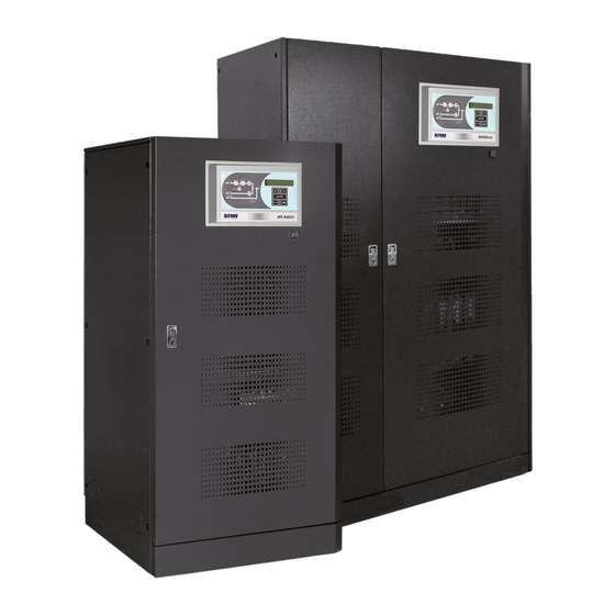
PRODUCT MANUAL
UNINTERRUPTIBLE POWER SUPPLIES
B9000FXS 60kVA (3PH / 3PH)
B9000FXS 80kVA (3PH / 3PH)
B9000FXS 100kVA (3PH / 3PH)
B9000FXS 125kVA (3PH / 3PH)
B9000FXS 160kVA (3PH / 3PH)
The present manual is an integrant part of the products technical back-up documentation. Read the warnings
with attention as they give important instructions concerning safety.
This equipment must be used only for its appointed operation. Any other use is to be considered incorrect and
therefore dangerous. The manufacturer cannot be held responsible for damages caused by incorrect, wrong and
unreasonable use.
Borri holds itself responsible only for the equipment in its original configuration.
Any intervention altering the structure or the operating cycle of the equipment has to be carried out and
authorized directly by Borri.
Borri cannot be held responsible of the consequences deriving from the use of non original spare parts.
Borri reserves its right to carry out technical modifications on the present manual and equipment without giving
any notice. If any typing errors or mistakes are detected, they will be corrected in the new versions of the
manual.
Borri holds itself responsible for the information given in the original version of the manual in Italian language.
Right of ownership – copying prohibited. Borri protects its rights on the drawings and catalogues by law.
Descrizione
Rev.
Description
F
Code upgrade
Borri S.p.A.
Via 8 Marzo, 2 – Soci
52010 Bibbiena (AR)
Tel. +39 0575 5351 – Fax +39 0575 561438
Web site: www.borri.it – e-mail: info@borri.it
Data
Date
20.05.13
E. Biancucci
Emesso
Approvato
Issued
Approved
F. Berti
English
Lingua
Pagina
di Pag.
Language
Page
of Pag.
E
1
54
Codice / Code
OMD10078
Advertisement
Table of Contents

Related Manuals for Borri B9000FXS 125kVA


Summarization of Contents
UPS General Description
Rectifier / Battery Charger
Converts AC input voltage to DC voltage for the inverter and battery.
Inverter
Converts DC voltage to AC voltage, stabilizing frequency and RMS value for the load.
Battery
Describes the battery system, its external cabinets, and charging logic.
Static Switch
Composed of thyristors, it handles power transfer between inverter and bypass lines.
Manual Bypass
Allows safe maintenance and testing by manually switching the load to the bypass line.
Operating Modes
Normal Operation
Standard mode where the rectifier feeds the inverter and battery, and inverter supplies the load.
Battery Operation
UPS operates from battery power during mains failure or rectifier failure.
Bypass Operation
Load is supplied directly from the mains bypass line, either manually or automatically.
Manual Bypass
Procedure for checking UPS functionality or during maintenance, with load on bypass.
Front Panel
Function Buttons
Details the five function keys on the UPS front panel for navigation and control.
Function of Mimic Panel LED's
Explains the status indicated by the LEDs on the UPS mimic panel.
Alarms and Operating Status
Lists all possible alarms and their codes, indicating system status.
Measurements on the Display
Describes the data displayed on the UPS screen, including voltage, current, and power.
General Technical Information
Technical Data
Refers to separate technical specifications for detailed product data.
Instructions for Installation
Provides guidelines for receiving, storing, and handling the UPS unit.
Handling of the UPS
Covers safe procedures and precautions for moving and handling the heavy UPS unit.
Positioning and Installation
Details environmental requirements, base plan, weights, and dimensions for installation.
Electrical Connection
Outlines mandatory grounding, cable selection, and connection procedures for mains and batteries.
Backfeed Protection Device
Explains the optional device that disconnects the bypass line during a mains failure.
Terminal Boards
Shows the layout and identification of terminal boards for power and auxiliary connections.
Connection of Power Cables
Specifies connections for battery, AC mains, and AC output power cables.
Connection of Auxiliary Cables
Details connections for external controls like manual bypass, generator, and EPO.
Serial Interfaces
Describes communication ports like RS232/USB, MODBUS, and SNMP for monitoring.
Positioning and Connection of Batteries
Guidelines for battery installation, including safety, ventilation, and cabinet requirements.
Options
Standard Options Included to be Set Via Software
Lists software-configurable options like Diesel generator mode and Off-line operation.
Options Provided on Request
Lists optional hardware features available for purchase, such as alarm cards and remote panels.
Need help?
Do you have a question about the B9000FXS 125kVA and is the answer not in the manual?
Questions and answers