Table of Contents
Advertisement
Advertisement
Table of Contents

Related Manuals for Leica M205 FCA


Summary of Contents for Leica M205 FCA
- Page 1 Leica M165 FC Leica M205 FA / M205 FCA User Manual...
-
Page 2: General Instructions
Use in clean rooms Servicing Before using your microscope for the first The Leica M series can be used in clean rooms Repairs may only be carried out by Leica time, please read the "Safety concept" book- without any problems. -
Page 3: Important Safety Notes
This User Manual describes the special func- To maintain the unit in its original condition and to ensure safe operation, the user must tions of the individual modules of the Leica M User Manual M2-267-1 for the motorized stereo microscopy series and contains impor- follow the instructions and warnings contained focus system. -
Page 4: Symbols Used
Figures Failure to comply can cause the following: Hazards to personnel (1) Numbers in parentheses within the Functional disturbances or damaged descriptions relate to the figures and the instruments items within those figures. Leica M Series User Manual... -
Page 5: Safety Instructions
Refer to "Safety Concept" booklet tion of Leica stereo microscopes of the M series. Place of use Ensure that: Intended use Refer to "Safety Concept" booklet The M series stereo microscopes and Refer to "Safety Concept"... - Page 6 The ergonomic design and construction of EC Declaration of Conformity the Leica M stereo microscopy series are Refer to "Safety Concept" booklet Transport intended to reduce the exertion of the user Use the original packaging for shipping or to a minimum.
- Page 7 UV filters are installed in the observation Fill empty filter positions with dummy filter beam paths to protect the eyes. carriers (e.g. M165 FC). The stray-light protection on the lamp Do not select a white, strongly reflective housing prevents irradiation of the hands.
- Page 8 (follow the manufacturer's specifications and the minute meter on the supply unit). To minimize the risk of explosion, replace a discolored mercury lamp promptly. Leica Microsystems assumes no liability for damage caused by exploding, incor- rectly installed or improperly used mercury lamps.
-
Page 9: Table Of Contents
Leica FluoCombi III – Adjusting the Parfocality Safety Instructions Leica FluoCombi III – Centering the Objectives Leica FluoCombi III – Filter and UV Protection Screen The Leica M Series for Fluorescence Transmitted-light Base Leica TL BFDF: Before First Use Congratulations! - Page 10 Leica TL BFDF Transmitted-light Base: Controls Iris Diaphragm Leica TL BFDF Transmitted-light Base: Operation Eyepieces Leica TL RC / Leica TL RCI: Controls Leica TL RCI: The Deflection Mirror Magnification Factors of the Eyepieces Leica TL RCI: Color Intensity and Temperature...
- Page 11 Leica MATS TL Fluorescence Specifications Filter Changer Leica M165 FC / Leica M205 FA / Leica M205 FCA FIM – Fluorescence Intensity Manager Leica EL6000 – Specifications About Fluorescence Microscopy (Only Applicable for Leica M205 FA) 119 Leica TL ST Transmitted-light Base...
-
Page 12: The Leica M Series For Fluorescence
The Leica M Series for Fluorescence Leica M Series User Manual The Leica M Series for Fluorescence... -
Page 13: Congratulations
It contains all the information you need regarding operation, safety and maintenance. Simply observing a few guidelines will ensure The Leica M series embodies all the qualities you associate with the name that even after years of intensive use, your stereo microscope will continue Leica Microsystems: excellent objectives, high-quality engineering, and to work as smoothly and reliably as on the very first day. -
Page 14: A Step Towards Infinity
* Leica M205 FA with 1.0× planapochromat and 10× eyepieces Leica M Series User Manual The Leica M Series for Fluorescence... -
Page 15: The Electronics: Comfort, Convenience And Safety For Your Experiments
Never before have electronics been used as Reliability for your experiments diaphragm and more and transmits the infor- extensively in a Leica series as in the new Exact reproducibility of results is an increas- mation to the Leica LAS software. Thus you M series lineup. -
Page 16: The Modular Design: Everything Is Relative
The optics carriers, eyepieces, bases that cannot be met with standard parts, contact and more can be combined in any way you your Leica consultant. We have a solution for choose, allowing you to create the microscope every problem. -
Page 17: Maximum Compatibility
Maximum Compatibility Leica engineers were careful to ensure that Tubes the new Leica M series – like its predecessors – The interface between the optics carrier and the remains compatible with existing series. This tube has remained the same, so existing tubes means that objectives, bases, tubes and so on fit the new M series. -
Page 18: On We Go
On We Go If your new Leica microscope has already been If, on the other hand, you are assembling For everything you need to know about the assembled and commissioned by your Leica the microscope yourself, continue with the correct use of fluorescence-related parts, refer to consultant, click here to skip through the instal- "Assembly"... -
Page 19: Assembly
Assembly Leica M Series User Manual Assembly... -
Page 20: Assembling The Focusing Column For Tl Bases
1. Securely install the column adapter on the 2. Securely screw the focusing column to the column using the four included screws. base using the six included screws. Tools used Hex socket screwdriver, 3 mm Leica M Series User Manual Assembly... -
Page 21: Assembling The Focusing Column With An Incident-Light Base
1. Place the focusing column on the side. drive. directly on the base; no extension plate is required. Tools used Hex socket screwdriver, 3 mm 2. Insert the four screws provided into the outer holes of the base. Leica M Series User Manual Assembly... -
Page 22: Motorized Focus: Restricting The Travel Path
Exception: If the power fails while the motorized focus is moving, the position data are lost. In this case, the calibration must be repeated using the Leica LAS software or the Leica SmartTouch. To do so, please consult the respective manual. -
Page 23: Optics Carrier
2. Press the optics carrier backwards to the ing column so that the screw fits into the focusing column and screw it in place using thread provided and the lug fits into the your other hand. groove. Leica M Series User Manual Assembly... -
Page 24: Tube
Tools used positioning screw meshes with the guide tion. No tools required. groove. Preparations 1. Unscrew the positioning screw and remove the protective cover. Leica M Series User Manual Assembly... -
Page 25: Eyepieces
You can extend the overall magnification range 2. Remove the plastic tube guard. using available 10×, 16×, 25× and 40× wide- field eyepieces for persons wearing glasses. 4. Securely tighten the clamping screws. Leica M Series User Manual Assembly... -
Page 26: Objective
This applies particu- Preparation larly to the 2× planapochromatic objective, If using the Leica FluoCombi III, read the 1. Remove the protective cap on the optics which is very heavy. Remove all specimens from instructions on page 30. -
Page 27: Uv Protection Screen: Assembly
UV filter and adjust it correctly. hexagon-head screw to the left or right side of the microscope carrier. • Always position the UV protection screen so that the operator can never look directly at the light spot. Leica M Series User Manual Assembly... -
Page 28: Objective Nosepiece - Assembly
3. Unscrew the three Phillips screws on the objective mount of the optics carrier and remove the intermediate ring. You can now adjust the parfocality (see instruc- tions on the next page). Leica M Series User Manual Assembly... -
Page 29: Objective Nosepiece - Adjusting Parfocality
5. Toggle to the 2× objective. 6. Select the strongest magnification and Preparation refocus until the specimen appears abso- Open the iris diaphragm. lutely sharp. Set the dioptric correction of the eyepieces to "0". Leica M Series User Manual Assembly... -
Page 30: Leica Fluocombi Iii - Preparations
Leica FluoCombi III – Preparations Before assembling the FluoCombi, you 2. Screw the two screws into the holes 4. Screw the other planapochromatic stereo have to disconnect all instruments provided for storage. objective into the FluoCombi III. from the power supply. Failure to observe these instructions can result in damage to the micro- scope and the connected instruments. -
Page 31: Leica Fluocombi Iii - Assembly
Leica FluoCombi III – Assembly 1. Guide the FluoCombi III in from below, 2. Hold the FluoCombi III securely and screw it while holding it flat. Ensure that it is aligned to the focusing column using the provided with the holder on the focusing column at screw. - Page 32 Leica FluoCombi III – Assembly (Continued) Assembling the optics carrier 2. Attach the optics carrier to the Fluo- 4. Assemble the tube (see page 24). 1. Unscrew the three screws and the adapter Combi III and screw it into place. ring on the optics carrier.
-
Page 33: Leica Fluocombi Iii - Adjusting The Parfocality
Leica FluoCombi III – Adjusting the Parfocality Setting up the objective nosepiece 1. Place a specimen under the microscope. 7. Unscrew the clamping screw on the The following configuration only has to objective. be carried out once. It ensures that the 2. - Page 34 Leica FluoCombi III – Adjusting the Parfocality (Continued) 9. By turning the objective ring, focus on the 11. Refocus. specimen until the specimen appears abso- lutely sharp. 12. Tighten the clamping screw (see Step 7). 13. Rotate the stereo planachromatic objective under the beam path.
-
Page 35: Leica Fluocombi Iii - Centering The Objectives
Leica FluoCombi III – Centering the Objectives The following configuration only has to Centering the objective 4. Center the objective over the specimen by be carried out once. It ensures that the 1. Rotate the 5× planachromat under the... -
Page 36: Leica Fluocombi Iii - Filter And Uv Protection Screen
Leica FluoCombi III – Filter and UV Protection Screen Inserting the dichroic mirror Assembling the UV protection screen 1. Pull the dummy filter carrier out of the 1. Screw the UV protection screen to the holder. holder provided on the optics carrier. -
Page 37: Transmitted-Light Base Leica Tl Bfdf: Before First Use
Transmitted-light Base Leica TL BFDF: Before First Use Removing the transport anchors • Before you can use the transmitted- light base for the first time, it is abso- lutely necessary to remove the two transport Anchor of mirror anchors. Anchor of switching slide... -
Page 38: Transmitted-Light Base Leica Tl Bfdf
Disassembly over those in the base. Stage assembly is performed in reverse order of the following The Leica TL BFDF transmitted-light base can be steps. 3. Attach the stage to the base with the four equipped with three different stages. -
Page 39: Leica Tl Rc / Leica Tl Rci
3. Attach the stage to the base with the four Stage assembly supplied hexagon-head screws. The Leica TL RC/ RCI transmitted-light base can be equipped with three different Leica stages. 4. Insert the glass plate back into the standard The selected stage is mounted on the base stage. -
Page 40: Leica Isopro Manual Mechanical Stage: Assembly
Leica IsoPro Manual Mechanical Stage: Assembly Leica IsoPro Mechanical Stage Before the Leica IsoPro mechanical stage is Left or right operation Before the Leica IsoPro mechanical stage is mounted to the base, the axis containing the If the controls are to be mounted on the left-... - Page 41 Leica IsoPro Manual Mechanical Stage: Assembly (Continued) 1. Take the glass plate from the mechanical Control assembly Mechanical stage assembly stage and turn it around. 1. Take the glass plate from the mechanical 1. Place the mechanical stage onto the base.
- Page 42 Leica IsoPro Manual Mechanical Stage: Assembly (Continued) 3. Attach the mechanical stage evenly to the Focusing drive and column three threaded holes. 1. Unscrew the extension plate from the base using the Allen key provided. 4. Now move the mechanical stage as far as it will go in the direction of the column.
-
Page 43: Leica Isopro Motorized Mechanical Stage: Assembly
Basics 1. Unpack the mechanical stage from the 2. Secure the motorized mechanical stage to The transmitted light bases of the Leica transport packaging and position it on the the base using three M4 screws. TL series (TL BFDF, TL RC, TL RCI) are supplied transmitted-light base. - Page 44 Leica IsoPro Motorized Mechanical Stage: Assembly (Continued) 3. Remove the two M3 screws and the holder 4. Remove the two M4 screws and the sleeve 5. Remove the four shock-absorbing cartons from the mechanical stage. from the mechanical stage. from the mechanical stage.
- Page 45 Leica IsoPro Motorized Mechanical Stage: Assembly (Continued) The bases Mechanical stage and base • The TL BFDF, TL RC and RCI transmitted-light Never move the sledge of the motor- bases can be equipped with three different ized mechanical stage manually in stages: Standard stage, manual and automated the X ...
- Page 46 CTL2 initializes and automatically drives to the mid interfaces. position. 2. Plug the CTL2 plug of the Leica PSC control- 4. Connect the PC (where applicable) and ler into another CTL2 interface. X/Y Stage DCI Module (using a suitable USB cable).
-
Page 47: Cables: Connections
Cables: Connections The new Leica M series features extensive The terminals The connection to the PC and to other instru- encoding with which various microscope data ments is made using the terminals on the rear and settings can be read out, transferred to the side of the column: PC and reproduced later. -
Page 48: Cables: Cable Duct
2. Remove the cover of the cable duct. Tip: Estimate the length of the cable ends you will need before screwing on the cover. For thick cables, it is difficult to change the length retroactively. Leica M Series User Manual Assembly... -
Page 49: Cables: Diagram
Cables: Diagram Alternative installation LED5000 SLI Please use the Leica Application Suite to configure the functions of the system. LED5000 RL LED5000 MCI DCI Controlbox for IsoPro motorized stage TL RCI Power/USB 115/230 V PC USB Footswitch(es) Handwheel Smart Move... -
Page 50: Leica Led5000 Mci
3. Plug the other end of the cable into one of the three "CTL2" sockets on the column. Constraints The Leica LED5000 MCI cannot be used together with the objective nosepiece. Leica M Series User Manual Assembly... -
Page 51: Leica Led5000 Mci: Alternative Assembly
For such purposes, the Leica LED5000 MCI is directly fastened to the column. Installation on the column 1. Pull the retaining stirrup out of the Leica LED5000 MCI. Leica M Series User Manual Assembly... -
Page 52: Leica Led5000 Rl: Assembly
50 mm and 80 mm. Constraints The Leica LED5000 RL can be used only in 2. Place the Leica LED5000 RL against the Continued on next page. conjunction with the planapochromat 1× and objective from below, push it up as far as it planapochromat 0.63×... - Page 53 For optimum accessibility of the speci- column without integrated electronics, men, the ring illuminator should be the Leica LED5000 RL must be supplied with installed with the cable facing backwards. power via an external power supply unit (not However, it is also possible to turn the ring included in the delivery package).
-
Page 54: Leica El6000 - Safety Notes
DIN VDE 0100-710. It is also not intended to be combined with medical devices as defined The responsible Leica affiliate or the main plant by EN 60601-1. If a microscope is electrically in Wetzlar must be consulted whenever the... - Page 55 Leica EL6000 – Safety Notes (Continued) • • • The Leica EL6000 compact light source The interior of the lamp inserted into the Only fuses of the specified type and generates high-energy light with invisi- unit contains highly toxic substances.
- Page 56 Leica EL6000 – Safety Notes (Continued) Electrical safety For indoor use only. Supply voltage 100–240 V~ (±10 %) Frequency 50–60 Hz Power consumption Max. 210 VA Fuses 5×20, 2.5 A, slow-blowing, breaking capacity H, see page 115 Ambient temperature 0–40 °C Relative humidity 10 %–90 %...
-
Page 57: Leica El6000 - Preparations
The lamp used in the instrument Inserting the lamp • Set up the Leica EL6000 so that the becomes very hot during operation and 1. Pull the power plug out of the socket, so front is readily accessible and visible. - Page 58 Leica EL6000 – Preparations (Continued) 4. Carefully lay the Leica EL6000 on its side so 5. Pull the pressure bolt back towards the Ensure that the groove in the contact surface of that the opening faces you. front plate using the lever.
- Page 59 Leica EL6000 – Preparations (Continued) 7. When the lamp makes full contact with the 9. Check to make certain that a heat-absorb- lamp mount, release the lever. ing filter has been inserted into the shaft in order to protect the connected light guide.
-
Page 60: Leica El6000 - Connection To The Fluorescence Lamp Housing
Leica EL6000 – Connection to the Fluorescence Lamp Housing • Always connect the light guide to the 2. Insert the adapter into the fluorescence 4. Insert the short end of the light guide into lamp housing of the stereo microscope... - Page 61 Leica EL6000 – Connection to the Fluorescence Lamp Housing (Continued) • 6. Insert the long end of the light guide into Only use a light guide with a light input the light output of the Leica EL6000. There of the type "Storz long", as otherwise must be a noticeable click.
-
Page 62: Leica El6000 - Replacing The Lamp
3. Remove the housing cover. differ from the installation procedure outlined on page 57, except for the fact that the existing 4. Carefully lay the Leica EL6000 on its side so lamp has to be removed first. that the opening faces you. -
Page 63: Leica El6000 - Using The Internal Shutter
Leica EL6000 – Using the Internal Shutter With the M205 FCA you can control a variety of Connecting the shutter cable Configuring the shutter fluorescence light sources, e.g. the EL6000 has Plug the cable into a free CAN port of your On the front panel of the lightsource is a switch a fast internal shutter. -
Page 64: Quick Start Guide
Quick Start Guide Leica M Series User Manual Quick Start Guide... -
Page 65: The Fastest Route To Success
The Fastest Route to Success Your Leica stereo microscope has been delivered in completely assembled condition by your Leica partner, and naturally you want to get right to work. Therefore, your next step should be to study the Quick Start Guide, which outlines the most important steps at a glance. -
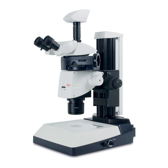
Page 66: Overview Of An M Series Microscope
1. Eyepieces for spectacle wearers with dioptric correction and eyecups 2. Trinocular tube 3. Fluorescence housing 4. Filter Changer 5. Display 6. Motorized Focus 7. Objective Nosepiece 8. Leica SmartTouch 9. UV protection screen Leica M Series User Manual Quick Start Guide... -
Page 67: The Correct Interpupillary Distance
Not to worry – after a little while, it will become automatic. Reference value The distance between eye and eyepiece measures approx. 22 mm for 10/23B wide-field eyepieces for persons wearing glasses. Leica M Series User Manual Quick Start Guide... -
Page 68: Using The Eyepieces
Each eyepiece offers a certain magnification grated dioptric correction, turn the value to factor that has a determinative effect on the the "0" mark. total magnification. Furthermore, all Leica eyepieces can be equipped with practical grati- cules that enable measuring and quantifying of specimens. -
Page 69: Focusing
1 µm. The outer, fine adjustment is used for fine • The focusing drive can be operated either focusing. The coarse/fine adjustment carries a left- or right-handed. load of up to 15 kg. Leica M Series User Manual Quick Start Guide... -
Page 70: Adjusting The Resistance Of The Focus Drive
1. Grip the outer drive knobs with both hands and turn them towards each other until the desired resistance is reached during focusing. Leica M Series User Manual Quick Start Guide... -
Page 71: Changing Magnification (Zoom)
Leica M165 = 16.5:1 Leica M205 = 20.5:1 3. Rotate the magnification changer until the desired magnification is configured. The rotary knob for the zoom can be used either left or right-handed. Leica M Series User Manual Quick Start Guide... -
Page 72: Ratchet Steps And Magnification Levels
2. Push the bottom button upwards to enable enabled, photographs, measurement results the ratchet steps. the eyepiece and objective combination used. etc. can be reproduced more accurately. Leica M Series User Manual Quick Start Guide... -
Page 73: Parfocality: More Comfort And Convenience For Your Work
For the procedure for adjusting the parfo- cality for the objective nosepiece, refer to page 29. For the procedure for adjusting the parfo- cality for the Leica FluoCombi III, refer to page 33. Leica M Series User Manual Quick Start Guide... -
Page 74: Iris Diaphragm
The "depth of field" (or "focus depth") is the area of a specimen that is brought into sharp focus. Leica M Series User Manual Quick Start Guide... -
Page 75: Eyepieces
Eyepieces Leica M Series User Manual Eyepieces... -
Page 76: Magnification Factors Of The Eyepieces
Order number 10× ± 5 diopter settings 10 450 630 16× ± 5 diopter settings 10 450 631 25× ± 5 diopter settings 10 450 632 40× ± 5 diopter settings 10 450 633 Leica M Series User Manual Eyepieces... -
Page 77: Health Notes
The risk can be kept to a minimum by using individual eyepieces or detachable eyecups. Eyecups can be ordered separately. Please contact your Leica partner. Separate eyecups are an effective way of preventing infections. Leica M Series User Manual Eyepieces... -
Page 78: Dioptric Correction
Dioptric Correction All Leica eyepieces are also available with built- Using the dioptric correction Note that when using dioptric correction, in dioptric correction, allowing the microscope 1. Set the dioptric correction of both the advantage of parfocality is lost – thus to be used without glasses even by those with eyepieces to the mid position ("0"... -
Page 79: Dioptric Correction And Parfocality
Dioptric Correction and Parfocality Leica stereo microscopes are parfocally Adjusting 7. Look into the eyepieces. matched. The prerequisite for this is the correct 1. Set the dioptric correction for both setting of the diopters and the parfocality. The eyepieces to "0". -
Page 80: Graticules
LAS software. The Leica graticules for length measurements and numbering are fitted in mounts and are inserted into the eyepieces. 1. Screw the insert off of the eyepiece. - Page 81 Photography & Video Leica M Series User Manual Photography & Video...
-
Page 82: Photography & Video
The "Leica Application Suite", or "LAS" for short, work. Research results can be presented in over the camera and need the capability for is, as it were, the digital extension of the Leica an attractive manner; measurements on the measurement, evaluation and more in addition M series microscopes. -
Page 83: Photo Tubes And C-Mounts
In addition to Leica DFC cameras with the stan- the image sensor of the camera. dardized C-mount interfaces, you can connect The Leica digital cameras are detailed in a sepa-... -
Page 84: Trinocular Video/Phototube 50
50 % of the light is diverted to the video/ photo beam path. Assembly Fasten the "trinocular tube 50 %" to the optics carrier instead of the binocular observation tube (refer to page 24). Leica M Series User Manual Photography & Video... -
Page 85: Trinocular Video/Phototube 100
Assembly guide all available light into the camera. Fasten the "trinocular tube 100 %" to the optics You can now photograph the specimen. carrier instead of the binocular observation tube (refer to page 24). Leica M Series User Manual Photography & Video... -
Page 86: Trinocular Video/Phototube 100 %: Ergotube 5
Assembly Before mounting the ErgoTube, please remove the transport lock screw under the tube. Other- wise the photo slider cannot be used. Leica M Series User Manual Photography & Video... -
Page 87: Microscope Carrier
Microscope Carrier Leica M Series User Manual Microscope Carrier... -
Page 88: The Objective Nosepiece
Older Leica objectives can continue to be used, but without parfocality during the objective change. Leica M Series User Manual Microscope Carrier... -
Page 89: Objectives And Optical Accessories
Objectives and Optical Accessories Leica M Series User Manual Objectives and Optical Accessories... -
Page 90: The Different Types Of Objectives
With planapochromatic objectives, the finest structures are visible with high contrast. The sophisticated apochromatic correction allows these objectives to attain the highest color brilliance and fidelity. Leica M Series User Manual Objectives and Optical Accessories... -
Page 91: Bases
Bases Leica M Series User Manual Bases... -
Page 92: Leica Tl St Transmitted-Light Base: Controls
Leica TL ST Transmitted-light Base: Controls Extension plate of the transmitted-light base TL ST Rear side of the transmitted-light base TL ST 1. Screws for changing the halogen lamp 2. Power connection socket 3. Power switch 1. Adapter plate for easy assembly of focusing drives 2. -
Page 93: Leica Tl St Transmitted-Light Base: Operation
Leica TL ST Transmitted-light Base: Operation Light intensity control Transmitted-light control Bright field The left control adjusts the intensity of the The transmitted-light base TL BFDF has a slider Bright field is suitable for examining translu- 12 V/20 W halogen illumination. -
Page 94: Leica Tl St Transmitted-Light Base: Changing Bulbs
Leica TL ST Transmitted-light Base: Changing Bulbs Changing the halogen lamp Changing bulbs Precautionary measures • Before you change the lamp, it is abso- 1. Unscrew the two screws on the heat sink When inserting the lamp, ensure that... -
Page 95: Leica Tl Bfdf Transmitted-Light Base: Controls
Leica TL BFDF Transmitted-light Base: Controls Adapter at the focusing drive Extension plate of the Transmitted-light base TL BFDF 1. Adapter plate for easy assembly of focusing drives 2. Standard stage 10 450 562 3. Button to toggle between bright field and... -
Page 96: Leica Tl Bfdf Transmitted-Light Base: Operation
"BF" ("bright field"). Turn the control as far as it will go towards "DF" ("dark field"). Transmitted-light control The Leica TL BFDF transmitted-light base has a control that switches the light from "bright field" to "dark field". Fingertip with bright field illumination... -
Page 97: Leica Tl Rc / Leica Tl Rci: Controls
Leica TL RC / Leica TL RCI: Controls Vertical column – transmitted-light base 3 4 5 adapter plate 1. Power switch 1. Heat sink of the integrated halogen illumina- 2. Power connection socket tion (only TL RCI) 3. USB socket, type B 2. -
Page 98: Leica Tl Rci: The Deflection Mirror
Leica TL RCI: The Deflection Mirror Tilted mirror Functions of the rotary knob The built-in mirror features one flat and one The rotary knob (1) fulfills the following tasks: concave side and can be rotated and moved. The concave side is intended for use at high Turning the deflection mirror from the flat magnifications to increase the NA of the base. -
Page 99: Leica Tl Rci: Color Intensity And Temperature
The transmitted-light base TL RCI has two elec- Using a USB mouse (only TL RCI) tronic potentiometers that control the color The Leica USB mouse controls the CCIC and intensity (1) and color temperature (2). dimming function of the TL RCI base. Connect the mouse to the corresponding USB port of the base. -
Page 100: Leica Tl Rc / Leica Tl Rci: Operation
Leica TL RC / Leica TL RCI: Operation Setting the relief contrast Depending on the flap position, a part of Increased contrast without relief is attained The two switches on the left side of the trans- the opening of the built-in Fresnel lenses are if both diaphragms are set to 45°. -
Page 101: Leica Tl Rci: Methods In Transmitted Light
Leica TL RCI: Methods in Transmitted Light Vertical bright-field illumination Inclined transmitted light Single-sided dark field Suitable for stained amplitude specimens with Suitable for semitransparent, opaque speci- Suitable for fixed specimens and fine structures. sufficient contrast. mens such as foraminifera and fish eggs. Move... -
Page 102: Leica Tl Rci: Relief Images
Leica TL RCI: Relief Images Starting position Positive relief contrast Negative relief contrast Suitable for semitransparent and transparent Suitable for semitransparent and transparent 1. Push the deflection mirror all the way back specimens. The phase structures look like hills. specimens. These settings result in a negative towards the column. - Page 103 Leica TL RCI: Relief Images (Continued) Dynamic relief contrast Constraints Suitable for semitransparent and transparent The relief methods provide good results from specimens. mid-zoom to high magnifications and with 1×, 1.6× and 2× objectives. In the lower zoom half and with weaker specimens, the object field...
-
Page 104: Using Filters
Daylight filter for Leica TL ST The transmitted-light bases TL RC and TL RCI slot in the filter holder. A daylight filter is also available for the Leica TL ST can be equipped with up to three filters – transmitted-light base. -
Page 105: Leica Isopro (Non-Motorized): Controls
Leica IsoPro (Non-motorized): Controls Operating the Leica IsoPro mechanical stage 1. To move the stage in the X direction, rotate the outer knob. 2. To move the stage in the Y direction, rotate the inner control ring. Leica M Series User Manual... -
Page 106: Leica Isopro (Motorized): Controls
Leica IsoPro (Motorized): Controls IsoPro X/Y Stage DCI module Leica PSC Controller 1. Sub-D interface for Leica SmartMove 1. Quick control/memory function 2. 3 CTL2 interfaces 2. Fine control in X direction 3. USB interface (type B) 3. Fine control in Y direction 1. -
Page 107: System Illumination
System Illumination Leica M Series User Manual System Illumination... -
Page 108: Leica Led5000 Mci
Leica LED5000 MCI Contact with the base • The Leica LED5000 MCI (for "Multi Contrast If the optics carriers are accidentally Illumination") is a universal high-output illu- lowered too far, contact between the minator. Three groups of 3 LEDs each can be base and MCI may result. - Page 109 The bottom row primarily provides contrast. The Leica LED5000 MCI can also be controlled by the LAS (Leica Application Suite) software. Maximum brightness Maximum contrast...
-
Page 110: Leica Led5000 Rl
10 increments. Touch either It is controlled using either the integrated or via of the two buttons to adjust the intensity in The Leica LED5000 RL has been designed for the Leica Application Suite (LAS). small increments. Hold a key to change the use with the 1.0×... -
Page 111: Leica El6000 - About The Instrument
Special features: Heat-absorbing filter intended for biological routine and research The Leica EL6000 compact light source has an When the cover is open, the holder for the heat work, including the examination of specimens automatic beam cover. This ensures that the filter can be accessed. - Page 112 When connecting the light guide to the light source or the microscope adapter, make sure not to kink or damage the light guide. Your Leica consultant will be glad to provide additional information about suitable light guides. Leica M Series User Manual...
-
Page 113: Leica El6000 - Operation
The running-time meter measures the burn- In the "open" position, the shutter of the ing time of the lamp, not the switch-on time Leica EL 6000 is open – regardless of the of the Leica EL6000 compact light source. The signal from the remote control. -
Page 114: Leica El6000 - Troubleshooting
Light guide damaged/defective Repair or replace If these actions do not fix the problem, send the Leica EL6000 compact light source to Leica service with an exact description of the malfunction. Leica M Series User Manual System Illumination... -
Page 115: Cleaning And Maintenance
Spare parts and accessories Permitted replacement fuses switch off the Leica EL6000 compact The only parts of the Leica EL6000 compact Fuse: 5×20, 2.5 A, slow-blowing, breaking capacity H light source. light source that may be replaced by the user Wickmann Series 181 www.wickmann.com... -
Page 116: Fluorescence
Fluorescence Leica M Series User Manual Fluorescence... -
Page 117: Filter Changer
M165 FC, M205 FA and M205 FCA. for use with the motorized Leica M205 FA / M205 FCA. The filter sets are labeled (see The scope of delivery of the Leica M205 FA / page 120). M205 FCA and Leica M165 FC includes three... -
Page 118: Fim - Fluorescence Intensity Manager
The advantage of this procedure is its absolute reproducibility and fast switching between the intensity levels. A separate FIM level can be stored for every fluorescence filter. Different intensities of fluorescence can thus be cali- brated to one another. Leica M Series User Manual Fluorescence... -
Page 119: About Fluorescence Microscopy (Only Applicable For Leica M205 Fa)
About Fluorescence Microscopy (Only Applicable for Leica M205 FA) Functional principle The Leica M Series The filter system Fluorescent substances light up when irradi- The Leica M series fluorescence stereo micro- The FLUOIII® filter system consists of a rapid ated with short-wave excitation light, and fluo-... -
Page 120: Rapid Filter Changers And Filter Types
560/40 nm (540–580 nm) Texas Red 560/40 nm (540–580 nm) 610 LP DsRED 545/30 nm (510–560 nm) 620/60 nm (590–650 nm) 620/60 nm (590–650 nm) 700/75 nm (663–737 nm) 555/60 nm (530–580 nm) 610/75 nm (573–648 nm) Leica M Series User Manual Fluorescence... -
Page 121: Simple Filter Holders
Three simple filter holders are included with If you want to block the mercury light for holders with fluorescence filters, always the Leica M165 FC and the Leica M205 FA / longer than that, activate the UV shutter. insert the included simple filter holders with M205 FCA. -
Page 122: Equipping The Filter Changer
Removing the simple filter holder Inserting the filter touching the filters in order to avoid The Leica M165 FC and the Leica M205 FA / 1. Place the filter into the filter changer. fingerprints. Clean dirty filters immediately M205 FCA are equipped at the factory with using a soft, lint-free cloth and pure alcohol. -
Page 123: Observation Without Fluorescence
Leica stereo microscope as they are described in to extend the lifetime of the light guide. Switch- the previous section of this User Manual. These... -
Page 124: Double Iris Aperture
Note that: The greater the depth of field, the darker the image becomes. In the same way, the exposure time becomes longer for photographs. The resolution decreases. Adjusting the double-iris diaphragm using the knurled ring Leica M Series User Manual Fluorescence... -
Page 125: Commissioning The Fluorescence System
(see User Manual M2-216-1). Do not correctly to protect the observer (see page 27). switch on the supply unit until you feel confi- dent using the Leica stereo microscope. • Follow all safety instructions when handling mercury lamps and the lamp housing! 1. -
Page 126: Accessories
Accessories Leica M Series User Manual Accessories... -
Page 127: Leica Hand Wheel And Foot Switch
Leica Hand Wheel and Foot Switch Up to five foot switches can be configured with a microscope system. They can be programmed in LAS or LAS X to control focus, filter wheel, illumination, and individual memory positions. The hand wheel is designed to control the motor focus. -
Page 128: Leica Smartmove
Leica Smart- Move and using the Leica Application Suite. For a detailed description of the functions and settings, please refer to the Leica SmartMove manual or the Leica Application Suite help file. Leica M Series User Manual Accessories... -
Page 129: Leica Smarttouch
For a detailed description of the functions and needs with freely programmable rotary knobs settings, please refer to the Leica SmartTouch and function buttons. manual or the Leica Application Suite help file. Controls The functions of the individual knobs and screen elements can be configured both directly on the Leica SmartTouch and using the Leica Application Suite. -
Page 130: Leica Psc Controller
Leica Application Suite are provided cal stage. mechanical stage quickly. in the software's help file. Connection Connect the Leica PSC controller and the Leica IsoPro motorized mechanical stage to the DCI box. Fine control of the mechanical stage The motorized Leica IsoPro mechanical stage offers an accuracy of up to 0.25 µm. -
Page 131: Dimensional Drawings
Dimensional Drawings Leica M Series User Manual Dimensional Drawings... -
Page 132: Leica M165 Fc
Leica M165 FC Leica M165 FC with transmitted-light stand and focusing column (dimensions in mm) Leica M Series User Manual Dimensional Drawings... - Page 133 Leica M165 FC (Continued) Leica M165 FC with transmitted-light stand TL RCI, manual cross-stage Leica IsoPro and manual focus max. 370 X = +-75 mm max. 370 Leica M Series User Manual Dimensional Drawings...
- Page 134 Leica M165 FC (Continued) Leica M165 FC with transmitted-light stand TL RCI and manual focus Leica M Series User Manual Dimensional Drawings...
-
Page 135: Leica M205 Fa
Leica M205 FA Leica M205 FA with transmitted-light stand TL BFDF, trinocular ErgoTube, DFC camera and motorized focus (dimensions in mm) Leica M Series User Manual Dimensional Drawings... - Page 136 Leica M205 FA (Continued) Leica M205 FA with transmitted-light stand TL RCI, trinocular ErgoTube, DFC camera and motorized focus Leica M Series User Manual Dimensional Drawings...
- Page 137 Leica M205 FA (Continued) Leica M205 FA with transmitted-light stand TL RCI, IsoPro mechanical stage, trinocular ErgoTube, DFC camera and motorized focus max. 410 X = +-75 mm max. 410 Leica M Series User Manual Dimensional Drawings...
-
Page 138: Leica M205 Fca
Leica M205 FCA Leica M205 FCA with transmitted-light base and focusing column (dimensions in mm) LEICA M205 FCA Leica M Series User Manual Dimensional Drawings... - Page 139 Leica M205 FCA (Continued) Leica M205 FCA with transmitted-light stand TL RCI, Leica IsoPro manual mechanical stage and manual focus max. 370 LEICA M205 FCA X = +-75 mm max. 370 Leica M Series User Manual Dimensional Drawings...
- Page 140 Leica M205 FCA (Continued) Leica M205 FCA with transmitted-light stand TL RCI and manual focus LEICA M205 FCA Leica M Series User Manual Dimensional Drawings...
-
Page 141: Leica Led5000 Mci
Leica LED5000 MCI Leica LED5000 MCI (dimensions in mm) 275.3 Leica M Series User Manual Dimensional Drawings... -
Page 142: Leica Led5000 Rl
Leica LED5000 RL Leica LED5000 RL (dimensions in mm) 58 mm Leica M Series User Manual Dimensional Drawings... -
Page 143: Leica Mats Tl
Leica MATS TL 10 447 275 10 447 164 Leica M Series User Manual Dimensional Drawings... -
Page 144: Specifications
Specifications Leica M Series User Manual Specifications... -
Page 145: Leica M165 Fc / Leica M205 Fa / Leica M205 Fca
Leica M165 FC / Leica M205 FA / Leica M205 FCA Leica M165 FC Leica M205 FA Leica M205 FCA Optical data Zoom 16.5 : 1 manual, coded 20.5 : 1 automated with Fusion- 20.5 : 1 manual, coded with... - Page 146 Leica M165 FC / Leica M205 FA / Leica M205 FCA (Continued) Leica M165 FC Leica M205 FA Leica M205 FCA Optics carrier 100 % apochromatic optical system CMO (Common Main Objective) lead-free Specific surface resistivity 2×1,011 Ω/mm (housing) discharge time <2 seconds from 1,000 V to 100 V...
- Page 147 Leica M165 FC / Leica M205 FA / Leica M205 FCA (Continued) Leica M165 FC Leica M205 FA Leica M205 FCA Additional objectives (non-parfocal) 1× planachromat, 0.8× planapochromat, 0.63× planapochromat, 0.5× planapochromat Interpupillary distance 50 mm–105 mm Wide-field eyepieces for persons 10×, 16×, 25×, 40×, with replaceable eyecups &...
- Page 148 Leica M165 FC / Leica M205 FA / Leica M205 FCA (Continued) Leica M165 FC Leica M205 FA / Leica M205 FCA Module System Stands, illuminators Transmitted light stands For bright field and bright/dark field, high-performance base: Bright field, single-sided dark field,...
-
Page 149: Leica El6000 - Specifications
EN 61000-3-3 Power consumption 120 W Harmonic currents EN 61000-3-2 Service life (manufacturer information) Average value 2,000 h The instrument fulfills the requirements of EC Directive 89/336/EEC and the EMC law of September 18, 1998 Leica M Series User Manual Specifications... - Page 150 After cooling off, the lamp power supply in the Switch-on delay Approx. 60 s after lighting the Leica EL6000 compact light source is automatically lamp switched on again. Interface Protection screen If no light guide is plugged into the light output of...
-
Page 151: Leica Tl St Transmitted-Light Base
Leica TL ST Transmitted-light Base Light source Halogen lamp 12V/20W Quick illuminant change Illuminated area 50 mm Power supply unit Input voltage 100–240 V~, frequency 50–60 Hz energy consumption 30 W max., ambient temperature 10–40 °C Connections Power plug, power switch Weight 7.4 kg... -
Page 152: Leica Tl Bfdf Transmitted-Light Base
Coated optics for increasing the color temperature Matching of high num. aperture Yes** Remote control options Yes*** AntiShock Pads Dimensions (W×H×D) 340×390×90 mm *With cold light source Leica CLS150 LS **Concave mirror *** With external light source Leica M Series User Manual Specifications... -
Page 153: Leica Tl Rc / Leica Tl Rci
Matching of high num. aperture Yes*** Yes*** Remote control options Yes**** AntiShock Pads Dimensions of base (W×H×D) 340×390×95 mm 340×440×95 mm *Single-sided **With cold light source Leica CLS150 LS ***Concave mirror ****With external light source Leica M Series User Manual Specifications... -
Page 154: Leica Tl5000 Ergo
Power Supply Matching of high num. aperture Anti-Shock Pads Size (W×H×D, in mm) 412 × 341 × 46 Accessories IsoPro cross-stage support – Integrated heating stage (optional) Integrated slide adapter (optional) ErgoRest (optional) – Leica M Series User Manual Specifications... -
Page 155: Leica Isopro Motorized Xy Stage
Leica IsoPro Motorized XY Stage Compatibility Leica incident light base and TL bases (TL BFDF, TL RC, TL RCI) Stage size (L × W × H) 335.5 mm × 370 mm × 41.5 mm Travel 152 mm × 102 mm (6" × 4") -
Page 156: Appendix
Appendix Leica M Series User Manual Appendix... -
Page 157: Calculating The Total Magnification And Field Of View Diameter
Calculation example: Magnification in the binocular tube: MTOT VIS = MO × ME × z × q × r N FOV ∅ OF: M O × z ×q ×r 1 × 25 × 4 × 1.5 × 1.25 = 187.5× Leica M Series User Manual Appendix... -
Page 158: Care, Maintenance, Contact Persons
(Switzerland) AG, CH-9435 Heerbrugg. away from the instruments. decades, your Leica microscope will continue to work as well as it did on the very first day. Plugs, optical systems and mechanical parts... - Page 159 Keep accessories in a dust-free place when Remove dust with a pneumatic rubber bulb not in use. or with a soft brush. Clean objectives and eyepieces with special optic cleaning cloths and with pure alcohol. Leica M Series User Manual Appendix...
- Page 160 CONNECT WITH US! Leica Microsystems (Schweiz) AG · Max-Schmidheiny-Strasse 201 · 9435 Heerbrugg, Switzerland T +41 71 726 34 34 · F +41 71 726 34 44 www.leica-microsystems.com...
Need help?
Do you have a question about the M205 FCA and is the answer not in the manual?
Questions and answers