Sign In
Upload
Download
Table of Contents
Contents
Add to my manuals
Delete from my manuals
Share
URL of this page:
HTML Link:
Bookmark this page
Add
Manual will be automatically added to "My Manuals"
Print this page
×
Bookmark added
×
Added to my manuals
Manuals
Brands
Eaton Manuals
UPS
9155 S
User manual
Eaton 9155 S User Manual
9155 & 9355 marine ups 8-10 kva, 50/60 hz (1-phase input) & 8-15 kva, 50/60 hz (3-phase input)
Hide thumbs
1
2
3
Table Of Contents
4
5
6
7
8
9
10
11
12
13
14
15
16
17
18
19
20
21
22
23
24
25
26
27
28
29
30
31
32
33
34
35
36
37
38
39
40
41
42
43
44
45
46
47
48
49
50
51
52
53
54
55
56
57
58
59
60
61
62
63
64
65
66
67
68
69
70
71
72
73
74
75
76
77
78
79
80
81
82
83
84
85
86
87
88
89
90
91
92
93
94
95
96
97
98
99
page
of
99
Go
/
99
Contents
Table of Contents
Bookmarks
Table of Contents
Table of Contents
1 Safety Instructions
Audience
CE Marking
User Precautions
Environment
Inquiries
2 Introduction
System Description
Active-Front Technology
Figure 2-1: Marine UPS Units 8-15 Kva Type Approved Models
Advanced Battery Management (ABM)
Hot Sync® Technology
DNV Type Approval and ABS Product Design Assessment
Basic System Configuration
3 Mechanical Installation
Delivery Check
Unpacking and Visual Inspection
Figure 3-1: Type Designation Label
4 Planning before Installation
Figure 4-1: Marine UPS Units 8-15 Kva
Table 4-1: the Floor Surface Must Withstand These Weights (Standard Models)
Table 4-2: the Floor Surface Must Withstand These Weights (TA Models)
5 Cabinet Installation
Maintenance Bypass Switch
Figure 5-1: Marine UPS Unit with Internal Input Transformer
Transformer Option
Figure 5-2: UPS with Battery Module(S) and the Rear Mounted Mechanical Bypass Switch
External Battery Cabinet Option
Battery Racks
Figure 5-3: UPS Unit with the Factory Installed Isolation Transformer
6 Electrical Installation
Power Cables and Protective Fuses
Wiring Procedure
UPS Models Without an Internal Transformer
Figure 6-1: the Location of the Power Terminals for UPS Unit Without an Internal Transformer
UPS Models with an Internal Input Transformer
Figure 6-2: the Location of the Power Terminals for UPS Unit with an Internal Input Transformer
Figure 6-3: Cable Connections into a Transformer Section
UPS Models with an Internal Output Transformer
Figure 6-4: the Location of the Power Terminals for UPS Unit with an Internal Output Transformer
Figure 6-5: Wiring Diagram of 9155 N-Model (3-Phase in / 1-Phase Out). for Cable and Fuse Sizes, See the Table 6-1
Figure 6-6: Wiring Diagram of Type Approved 9155 N-Model (3-Phase in / 1-Phase Out). for Cable and Fuse Sizes, See the Table 6-1
Table 6-1: Recommended Cable and Fuse Sizes for 9155 N-Model (no Transformer)
Figure 6-7: Wiring Diagram of 9155 NT-Model with Internal MBS (3-Phase in / 1-Phase Out). for Cable and Fuse Sizes, See the
Figure 6-8: Wiring Diagram of Type Approved 9155 NT-Model with Internal MBS (3-Phase in / 1-Phase Out). for Cable and Fuse
Table 6-2: Recommended Cable and Fuse Sizes for 9155 NT-Model
Figure 6-9: Wiring Diagram of 9155 S-Model (1-Phase in / 1-Phase Out). for Cable and Fuse Sizes, See the Table 6-3
Figure 6-10: Wiring Diagram of Type Approved 9155 S-Model (1-Phase in / 1-Phase Out). for Cable and Fuse Sizes, See the Table
Figure 6-11: Wiring Diagram of 9155 ST-Model with Internal MBS (1-Phase in / 1-Phase Out). for Cable and Fuse Sizes, See the
Figure 6-12: Wiring Diagram of Type Approved 9155 ST-Model with Internal MBS (1-Phase in / 1-Phase Out). for Cable and Fuse
Table 6-3: Recommended Cable and Fuse Sizes for 9155 S Model and 9155 ST Model
Figure 6-13: Wiring Diagram of 9355 N-Model (3-Phase in / 3-Phase Out). for Cable and Fuse Sizes, See the Table 6-4
Figure 6-14: Wiring Diagram of Type Approved 9355 N-Model (3-Phase in / 3-Phase Out). for Cable and Fuse Sizes, See the Table
Figure 6-15: Wiring Diagram of 9355 NT-Model (3-Phase in / 3-Phase Out). for Cable and Fuse Sizes, See the Table 6-4
Figure 6-16: Wiring Diagram of Type Approved 9355 NT-Model (3-Phase in / 3-Phase Out). for Cable and Fuse Sizes, See the
Table 6-4: Recommended Cable and Fuse Sizes for 9355 N-Model and 9355 NT-Model
External Battery Cabinet (EBC) Installation Procedure
Figure 6-17: Connections of the UPS Unit and External Battery Cabinets
Figure 6-18: Cable Connections of the External Battery Cabinet
Figure 6-19: to Minimise Safety Risk Remove + or - Cable from Battery String before Connecting UPS and Ebcs
7 Software and Connectivity
Communication Cables
Figure 7-1: Location of Control Cable Terminals: Signal Inputs (X44 & X45); EPO (NC (X12) & no (X52)); RS-232 (X53); Relay
Connection to the Standard RS-232 Port (X53)
Lansafe Software
Figure 7-2: Identification of the Interface Port Pins
External Control Connections
Emergency Power off (EPO)
Figure 7-3: External Control Cable Connections to the UPS
Relay Outputs
Programmable Signal Inputs
EPO Relay (Option)
Figure 7-4: EPO Relay and the Connection Diagram
Earth Fault Monitor (Option)
Xslot Communication (Option)
Figure 7-5: Earth Fault Monitor and the Connection Diagrams for 9155 and 9355 Models
Figure 7-6: Location of Empty Xslot Bays
Table 7-1: Typical Xslot Configurations for UPS Communication
Web/Snmp Module (Optional)
AS400 Relay Module (Optional)
Figure 7-7: Connectups-X Web/Snmp Module and Environmental Monitoring Probe
Figure 7-8: AS400 Relay Module
Single Serial Port Module (Optional)
Figure 7-9: Modus/Jbus Module
Modus/Jbus Module (Optional)
8 User Operations
Display Functions
User Settings
Table 8-1: Menu Map for Display Functions
Changing Charging Current
Changing Language
Configuring User Settings
Table 8-2: User Setting in the LCD Menu Screen
Using Relay Outputs
Normal Start-Up
Table 8-3: Required Battery Charge Currents
Battery Start-Up
Start-Up after EPO
Shutdown
9 Maintenance
Regular Service/Intervals
Table 9-1: Typical Alarms Displayed in the LCD Screen of the UPS Unit
Batteries
Cooling Fan
LED Indicators
Table 9-2: Routine Maintenance Intervals Recommended by the Manufacturer
Maintenance Bypass Switch (MBS) Operation
Internal Maintenance Bypass Switch Operation
Table 9-3: Description of the LED Indicators
Figure 9-1: the Normal (UPS Supplying the Load) Positions of the MBS Switches
Figure 9-2: the Normal Positions of the MBS Switches
Turn UPS from Normal Mode to Mechanical Bypass
Figure 9-3: the Positions of the MBS Switches in the Mechanical Bypass Mode
Turn UPS from Mechanical Bypass to Normal Mode
Maintenance Bypass Switch Operation
Turn UPS from Normal Mode to Mechanical Bypass
Figure 9-4: the Normal (UPS Supplying the Load) Positions of the MBS Switches
Figure 9-5: the Normal Positions of the Three MBS Switches
Turn UPS from Mechanical Bypass to Normal Mode
Figure 9-6: the Positions of the Three MBS Switches in the Mechanical Bypass Mode
Figure 9-7: the Normal Positions of the MBS Switches in the Normal Mode
10 Parallel Systems
Overview
Figure 10-1: Parallel Configurations with UPS Modules
Tie Cabinets
Figure 10-2: Dimensions of the Tie Cabinet
Figure 10-3: Cable Routing of the Tie Cabinet: 1-Phase Model on the Left and 3-Phase Model on the Right
Figure 10-4: 1-Phase Tie Cabinet's Wiring Diagram with Three UPS Units
Figure 10-5: 1-Phase Tie Cabinet's Wiring Diagram with Two UPS Units and Bypass Connected
Figure 10-6: 3-Phase Tie Cabinet's Wiring Diagram with Three UPS Units
Table 10-1: Minimum Cable and Fuse Rating for the Different Parallel System with Installation Procedure C * (System Bypass Not Allowed)
Figure 10-7: 3-Phase Tie Cabinet's Wiring Diagram with Two UPS Units and Bypass Connected
Table 10-2: Minimum Cable and Fuse Rating for the Different Parallel System with Installation Procedure C * (System Bypass Not Allowed)
Xslot Hot Sync Card: Installing and Wiring
Figure 10-8: Bypass Wiring Diagram and Cable Length Notes
Figure 10-9: Xslot Hot Sync Card and Terminal Interface
Table 10-3: Description for Figure Xslot Hot Sync Card and Terminal Interface
Figure 10-10: Communication Cabling Wiring
Figure 10-11: Xslot Hotsync Card and Jumper Settings
Table 10-4: Communication Wiring Termination
Parallel Operations
11 Recycling the Used UPS or Batteries
Figure 11-1: WEEE Symbol
Figure 11-2: Recycling Batteries Symbol
12 Dimensional Drawings
Figure 12-1: Standard and Type Approved Marine UPS Models with One Bottom Battery Module
Figure 12-2: Standard and Type Approved Marine UPS Models with Two Bottom Battery Modules
Figure 12-3: Standard and Type Approved Marine UPS Models with One Bottom Transformer Module
Figure 12-4: Standard and Type Approved Marine UPS Models with Middle Battery and Bottom Transformer Module
Figure 12-5: Standard and Type Approved Marine UPS Models with no Battery or Transformer Modules
Figure 12-6: External Battery Cabinet Models with Two and Three Modules
13 Wiring Diagrams for Internal Transformer
Figure 13-1: Internal Transformer Wirings for 9155 NT Model
Figure 13-2: Internal Transformer Wirings for 9155 ST Model
Figure 13-3: Internal Transformer Wirings for 9355 NT Model
14 Technical Data
Table 14-1: Standards
Table 14-2: Environment
Table 14-3: Mechanical Configuration
Table 14-4: Characteristics
Table 14-5: AC Input
Table 14-6: DC Circuit
Table 14-7: AC Output
15 Warranty
Advertisement
Quick Links
Download this manual
Eaton 9155 & 9355 MARINE UPS
P-164000341
8-10 kVA, 50/60 Hz (1-phase input) & 8-15 kVA, 50/60 Hz (3-phase input)
User's Guide
Table of
Contents
Previous
Page
Next
Page
1
2
3
4
5
Advertisement
Table of Contents
Need help?
Do you have a question about the 9155 S and is the answer not in the manual?
Ask a question
Questions and answers
Related Manuals for Eaton 9155 S
UPS Eaton Powerware 9155 UPS20-30kVA User Manual
230v 50/60 hz output (3-phase input/1-phase output) (52 pages)
UPS Eaton 9155 User Manual
Bypass power module (bpm) (28 pages)
UPS Eaton Powerware 9x55 series Upgrade Procedure
8-15 kva battery upgrade (26 pages)
UPS Eaton 9155 User Manual
Parallel ups 8–15 kva (68 pages)
UPS Eaton 9155 Manual
(28 pages)
UPS Eaton 9155 Installation Instructions Manual
Ups seismic kit (10 pages)
UPS Eaton E.T.N 1500 VA - 60kVa Reference Manual
(500 va – 60 kva) (120 pages)
UPS Eaton UPS 9155 8-15 kVA Manual
Powerware series 8-15 kva (8 pages)
UPS Eaton Eaton 9155 Specifications
Powerware series 8-15 kva (8 pages)
UPS Eaton Powerware 9155 User Manual
Double-conversion, split-phase, online uninterruptible 8–15 kva power system (ups) (90 pages)
UPS Eaton 9155 User Manual
8–15 kva (92 pages)
UPS Eaton Powerware 9155 User Manual
Parallel ups 8–15 kva (66 pages)
UPS Eaton 9155 User Manual
Parallel ups 8–15 kva (68 pages)
UPS Eaton 9155 N User Manual
9155 & 9355 marine ups 8-10 kva, 50/60 hz (1-phase input) & 8-15 kva, 50/60 hz (3-phase input) (99 pages)
UPS Eaton 9155 UPS User Manual
(98 pages)
UPS Eaton 9130 Series Firmware Upgrade Instructions
Dsp (11 pages)
Summarization of Contents
Safety Instructions
Audience and Scope
Defines the intended readers and scope of the safety information provided.
CE Marking and Compliance
Details the CE marking compliance with European directives and harmonized standards.
User Precautions and Warnings
Outlines permitted user operations and crucial safety warnings for UPS handling.
Environmental Requirements
Specifies installation environment conditions, temperature, and dust considerations.
Inquiries and Support
Provides guidance on whom to contact for inquiries about the UPS and battery cabinet.
Introduction to the UPS System
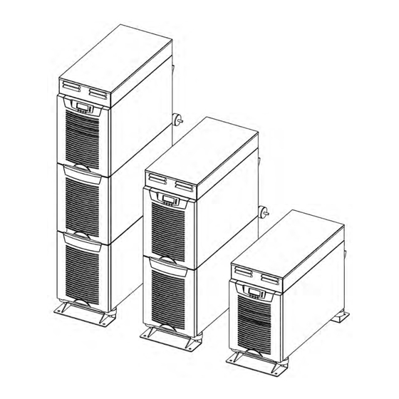
System Description
Overview of the UPS system's purpose, functionality, and design for marine applications.
Advanced UPS Technologies
Explains Active-Front technology, ABM, and Hot Sync technology for enhanced performance.
Type Approvals and System Configuration
Details DNV/ABS type approvals and common UPS system configurations.
Mechanical Installation Procedures
Delivery Check and Unpacking
Instructions for checking delivery contents and performing visual inspection.
Cabinet Installation
Maintenance Bypass Switch
Describes the maintenance bypass switch (MBS) options and installation.
Transformer and Battery Options
Details transformer options, external battery cabinet placement, and battery racks.
Electrical Installation and Wiring
Power Cables and Protective Fuses
Guidance on selecting and installing power cables and protective fuses.
Wiring Procedures for UPS Models
Details wiring procedures for different UPS models including transformer configurations.
External Battery Cabinet (EBC) Installation
Step-by-step procedure for installing external battery cabinets.
Software and Connectivity Options
Communication Cables and RS-232 Port
Information on communication cables, RS-232 port, and LanSafe software connection.
External Control Connections
Details on EPO, relay outputs, signal inputs, and optional modules for control.
XSlot Communication Modules
Overview of available XSlot communication modules like Web/SNMP, AS400, Serial, Modbus.
User Operations and Settings
Display Functions and Navigation
Describes the LCD display functions, menu structure, and navigation.
User Settings and Configuration
Guides users through configuring settings like language, alarms, and battery charging.
Operating Procedures
Instructions for normal start-up, battery start-up, EPO start-up, and shutdown.
Maintenance and Service
Maintenance Bypass Switch (MBS) Operation
Detailed procedures for operating the Maintenance Bypass Switch (MBS).
Regular Service Intervals
Recommends intervals for battery changes, battery tests, and cooling fan replacement.
LED Indicators
Explains the meaning of the UPS unit's LED indicators for status and alarms.
Parallel System Configurations
Overview and Configurations
Explains parallel UPS configurations for redundancy and capacity.
Tie Cabinets
Describes the function and wiring of Tie Cabinets for parallel UPS systems.
XSlot Hot Sync Card Installation
Instructions for installing and wiring the XSlot Hot Sync card for parallel operation.
Parallel Operations
Step-by-step guide for starting up and shutting down parallel UPS systems.
Recycling and Disposal
Dimensional Drawings
Internal Transformer Wiring Diagrams
Technical Data and Specifications
Standards and Approvals
Lists relevant standards, EMC, safety, and product approvals.
Environmental Specifications
Details ambient temperature, humidity, altitude, and vibration requirements.
Mechanical Configuration
Provides dimensions, weight, and color information for UPS models.
AC Input Specifications
Specifies input voltage, frequency, power factor, and rated input current.
DC Circuit and Battery Data
Details battery management, nominal voltage, quantity, and charging parameters.
AC Output Specifications
Lists active power, number of phases, frequency, and overload capabilities.
Warranty Information
Table of Contents
Print
Rename the bookmark
Delete bookmark?
Delete from my manuals?
Login
Sign In
OR
Sign in with Facebook
Sign in with Google
Upload manual
Upload from disk
Upload from URL
Need help?
Do you have a question about the 9155 S and is the answer not in the manual?
Questions and answers