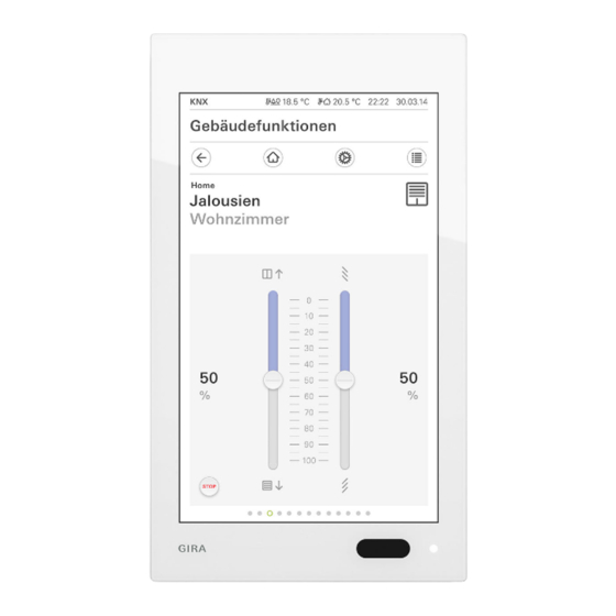
Summarization of Contents
For Your Safety
1.1 Area of Application
Defines the intended use of the Gira G1 for indoor environments and non-hazardous equipment control.
1.2 General Safety Instructions
Crucial safety guidelines covering electrical hazards, professional installation requirements, and prohibition of self-repair.
Overheating Protection Measures
Explains the automatic shutdown mechanism to prevent device damage from overheating due to improper placement or obstruction.
Handling Precautions for Component Integrity
Advises against dropping, modifying, or mishandling the device, especially its glass components, to prevent damage.
Device Description
Gira G1 Main Components
Identifies the key parts of the Gira G1: connection module, holding frame, and display module.
2.1 Flush-Mounted Connection Modules
Introduces the three types of connection modules (PoE, 230 V, 24 V) that the Gira G1 can be attached to.
2.1.1 PoE Connection Module Details
Provides a detailed view of the PoE connection module's front and rear, including its electronic interface and connection points.
2.1.2 230 V Connection Module Details
Details the 230 V connection module, showing its front and rear views, electronic interface, and the 230 V terminal.
2.1.3 24 V Connection Module Details
Details the 24 V connection module, showing its front and rear views, electronic interface, and the 24 V plug terminal.
2.2 Holding Frame Description
Describes the holding frame, including its front view features like loudspeaker, fastening slots, and cut-outs for sensors.
2.3 Display Module Description
Details the display module's side and bottom views, highlighting its release opening, sound channel, and microphone openings.
2.4 Scope of Supply
Lists all components and accessories provided in the Gira G1 package.
Mounting Devices
Electrical Safety During Mounting
Emphasizes the critical risk of electric shock during mounting and mandates installation by qualified electricians only.
3.1 Unpacking and Device Inspection
Instructions for carefully unpacking, verifying contents, and preparing the device for installation.
3.2 Installation Site Selection
Guidance on choosing an optimal installation location, including space requirements and recommended mounting height.
3.3 Mounting Preparation and Recommendations
Provides essential preparation advice, recommending specific cables and boxes for the Gira G1 PoE to ensure smooth installation.
3.3 Connecting Flush-Mounted Modules
Introduces the procedure for connecting the Gira G1 to its compatible flush-mounted connection modules.
3.3.1 Connecting PoE Module Cap
Details the initial step of opening the connection cap on the PoE module using a screwdriver for subsequent wiring.
3.3.2 Connecting 230 V Module
Step-by-step guide for wiring the 230 V connection module, covering cable preparation and connection terminal use.
3.3.3 Connecting 24 V Module
Step-by-step guide for wiring the 24 V connection module, covering cable preparation and plug terminal use, noting polarity irrelevance.
3.4 Inserting and Fixing Connection Module
Instructions for inserting the connection module into the device box and securing it with screws, emphasizing correct orientation.
3.5 Holding Frame Fastening Options
Outlines the two primary methods for securing the holding frame, depending on the number of flush-mounted device boxes used.
3.5.1 Fastening Frame with Dowels and Screws
Details the process of attaching the holding frame using dowels and screws, including marking and drilling points on the wall.
3.5.2 Fastening Frame Over Multiple Boxes
Explains the method of fastening the holding frame across two flush-mounted device boxes using appropriate screws.
3.6 Attaching the Display Module
Guides the user through the final step of attaching the display module to the holding frame until it securely clicks into place.
Cleaning and Maintenance
Touch Screen Cleaning Instructions
Provides essential advice on safely cleaning the glass touch screen, recommending specific materials and avoiding harsh chemicals.
Device Disassembly
Electrical Safety During Disassembly
Warns of the inherent electrical risks during disassembly and reiterates that only qualified electricians should perform this task.
5.1 Display Module Removal
Step-by-step guide on how to unlock the display module using a release tool or screwdriver for removal.
5.2 Complete Disassembly Procedure
Details the full process of disassembling the Gira G1, from removing the display to disconnecting the power supply.
Product Disposal
Environmental Disposal Guidelines
Advises on responsible disposal of electronic waste, stressing compliance with local regulations and avoiding household waste streams.
Technical Specifications
Gira G1 Model Specifications
Presents detailed technical data for the Gira G1, covering its application, dimensions, display, and performance metrics.
Connection Module Technical Data
Lists specific technical details for the flush-mounted connection modules, including electrical ratings, network standards, and physical characteristics.
Product Warranty Information
Warranty Claim Submission Process
Outlines the procedure for submitting warranty claims, including packaging faulty devices and providing necessary documentation.


Need help?
Do you have a question about the 2077 12 and is the answer not in the manual?
Questions and answers