Table of Contents
Advertisement
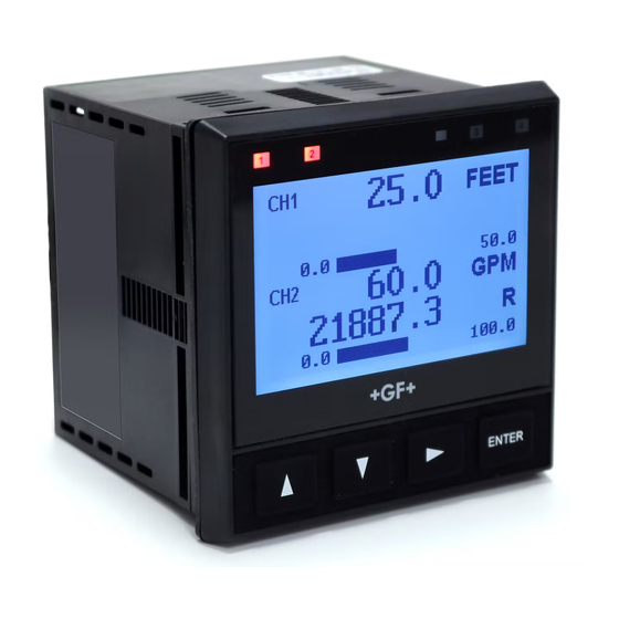
Signet 9950 Dual Channel Transmitter
*3-9950.090*
3-9950.090 Rev. C 05/17
3-9950-1, -2
NOTE:
Prior to installation, Check
www.gfsignet.com
software updates to your
device. See page 48, Field
Software Update, for more
information.
Description
The 9950 Dual Channel Transmitter is a two channel controller that can support
two sensors of same or different types in one instrument. The sensor types
supported by the 9950 are Signet Flow, pH/ORP, Conductivity/Resistivity, Salinity,
Temperature, Pressure, Level, Dissolved Oxygen, and devices that transmit a
4 to 20 mA signal with the use of the 8058 iGo
The 9950 includes advanced features such as derived functions, advanced
multiple relay modes, and timer based relay functions. Derived functions allows
for the control of a relay or current loop with the sum, delta (difference), or ratio
of two measurements. Multiple relay modes allow up to three signals to be used
for the control of a single relay, and can be any combination of analog and binary
inputs. The timer relay modes allow a relay to be activated on a repeating basis
from every minute to once every 30 days. Weekday timer mode allows a relay to
be energized, on a specifi c day or days of the week at a specifi c time.
The 9950 supports the following relay modules:
•
Four Channel Mechanical Relay Module
•
Two Mechanical and Two Solid State Relay Module
•
Two Mechanical Relays and Four Binary Inputs Module
for
Compatibility
The 9950 is compatible with all GF Signet
products listed in the column to the right.
● pH and ORP electrodes require the
Signet 2750 or 2751 DryLoc
Electronics (sold separately).
● Conductivity/Resistivity
measurement requires the Signet
2850 Conductivity/Resistivity Sensor
Electronics (sold separately).
•
English
•
Deutsch
•
Español
•
中文
Operating Instructions (see pg. 10)
®
Signal Converter.
Sensor
Model
515/8510
525
2000
2100
2250
2350
®
Sensor
2450
2507
2536/8512
2537-5
2540
2551
2552
U1000
U3000
U4000
2260
2270
2290
2291
2610-41
2724-2726
2734-2736
2750/2751
2756-2757
2764-2767
2774-2777
2819-2823
2839-2842
2850
English
Freq
Digital (S
L)
Requires
3
Output
Output
8058
X
X
X
X
X
X
X
X
X
X
X
X
X
X
X
X
X
X
X
X
X
X
X
X
X
X
X
X
X
X
X
X
X
X
X
Advertisement
Table of Contents

Related Manuals for GF 3-9950-1


Summarization of Contents
Signet 9950 Transmitter Overview
Product Description and Features
Describes the 9950 transmitter, its channels, and advanced features.
Supported Relay Module Types
Lists the optional relay modules compatible with the 9950.
Device Compatibility Information
Lists compatible GF Signet products and sensor electronics requirements.
Safety and Installation Guidelines
Essential Safety Precautions and Warnings
Covers reading the manual, handling, and general safety.
Hazard Symbols and PPE Guidance
Explains warning symbols and required personal protective equipment.
Panel Mounting and Installation Details
Provides dimensions for panel cutout and thickness.
Terminal Identification and Specifications
Power Terminal Connections and Types
Identifies DC and AC power terminals and their specifications.
Module, Input, and Output Terminal Descriptions
Describes module slots, channel inputs, loop outputs, and USB.
Available Relay Module Configurations
Lists the different types of relay modules available for the 9950.
Sensor Wiring Configurations
Frequency Output Sensor Wiring Guide
Wiring details for sensors providing frequency output.
Digital (S³L) Input Sensor Wiring Guide
Wiring details for sensors providing Digital (S³L) output.
Specific Sensor Wiring Notes and Examples
Wiring notes for specific sensors like 3-2610-41.
Advanced Sensor Wiring Details
Blind Magmeter Wiring and Configuration
Wiring and settings for 2551-XX-11 magmeter.
Magmeter Wiring and Technical Notes
Wiring and configuration notes for 2552 magmeter.
Power Wiring Diagrams and Safety
Wiring Diagrams for DC and AC Power Inputs
Illustrates connections for 3-9950-1 and 3-9950-2.
Power Wiring Safety Precautions
Warns against connecting AC to DC and electrical hazards.
Relay Module Wiring and Binary Inputs
Wiring for Mechanical and Solid State Relay Modules
Details for 3-9950.393-1 and -2.
Wiring for Binary Input Relay Module
Details for 3-9950.393-3.
Binary Input Specifications and Ratings
Details on voltage, current, and logic levels for binary inputs.
Device Operation and Initial Setup
Understanding Keypad Functions for Navigation
Explains how the keypad buttons operate.
Step-by-Step Basic Setup Procedure
Guides the user through initial configuration like language and time.
Password Management and Interface Navigation
Password System Overview and Types
Explains STD and CODE passwords and their purpose.
Display Layout and Menu Navigation Keys
Describes the screen elements and how to navigate menus.
Warranty and Product Registration
Warranty Information and Return Procedures
Details on warranty terms and repair returns.
Product Registration Methods
Instructions for registering the product online or via PDF.
Physical Dimensions and Module Installation
Device Dimensions and Mounting Views
Front and side views with measurements.
Module Installation and Removal Procedures
Steps for installing and removing plug-in modules.
Module Installation Safety Precautions
Warnings for ESD and high-voltage power sources.
Plug-In Modules and Relay Features
Overview of Optional Plug-In Modules
Lists available modules and their part numbers.
Relay Module Types and Characteristics
Differentiates dry-contact vs. solid-state relays.
Binary Input Functionality and Module Notes
Explains binary inputs and module-specific notes.
Sensor Signal Types and Wiring Considerations
Frequency Output Signal Type Details
Max cable length, wiring for frequency sensors.
Digital (S³L) Output Signal Type Details
Max cable length, wiring for S³L sensors.
4-20 mA Input and Relay Function Setup
Connecting and Configuring 4-20 mA Inputs
Wiring the 8058 converter and input menu setup.
Setting Relay Functions and Parameters
Step-by-step guide to configure relay behavior.
Advanced Relay Modes Explained
Setpoint-Based Relay Modes: Low and High
Explains Low/High Setpoint modes with hysteresis.
Time-Based Relay Mode: Cycle High/Low
Describes Cycle High/Low mode and its conditions.
Specialized Relay Modes
Window In/Out Relay Operation
How relays activate based on value ranges.
Proportional Pulse Operation Configuration
Setting up pulsing based on process value.
Pulse Width and Volume-Based Relay Modes
Pulse Width Modulation (PWM) Mode
Varies ON/OFF time proportionally.
Volumetric and Totalizer Pulse Modes
Activates relays based on fluid volume registered.
Complex Relay Logic and Timer Modes
Multiple Source Relay Logic Operators
Using Boolean logic (A|B|C, A&B&C) for relays.
Timer Modes: Period and Weekday Activation
Setting relays based on time intervals or specific days.
Derived Functions for Measurement Analysis
Types of Derived Measurements: Ratio, Delta, Sum
Basic derived function calculations.
% Passage and % Reject Calculations
Specific conductivity-based derived functions.
% Recovery Calculation Methods
Methods for calculating recovery in RO systems.
Menu System Navigation and Management
Understanding View and Menu Modes
How to switch between display modes.
Error Handling and Display Scrolling
Managing error messages and screen scrolling.
Password Management and Reset Procedures
Setting and resetting passwords.
Common Menu Structures and Settings
Overview of Common Menu Types
General menu structure.
INPUT Menu Configuration Options
Settings within the INPUT menu.
LOOP Menu Parameters and Settings
Detailed settings for the LOOP menu.
Relay Menu Configuration Details
Relay Source, Mode, and Binary Input Settings
Selecting sources, modes, and binary inputs.
Relay Parameters: Label and Set Low
Configuring relay labels and low setpoints.
Relay Menu Advanced Parameters
Relay Setpoints, Timing, and Pulse Settings
Set High, Set Volume, On Delay, Pulse Min/Max.
Pulse Width Modulation (PWM) and Cycle Time Settings
PWM parameters and cycle time.
Relay and Option Menu Settings
Additional Relay Menu Settings
Pulse Width, Set Total, Activate, Test Relay.
Core Option Menu Settings: Language, Date, Time
Language, time format, date, units.
Advanced Option Menu Configurations
Backlight, Display, and Bar Graph Settings
Controls for backlight and display modes.
Channel Settings, Functions, and Password Type
Decimal places, derived functions, password type selection.
Common View Mode Displays Explained
Memo, Generation, and User Manual Access
Information screens and manual access.
Measurement Value and Derived Function Displays
How different measurements are shown.
Loop Output and Relay/Binary Status Indicators
Displays for loop output and relay/binary status.
System Configuration and Calibration Access
System Configuration and Generation Information Screens
SYS CONFIG and Generation displays.
Date/Time Display and EasyCal Entry Point
Viewing date/time and accessing EasyCal.
Flow Sensor Specific Setup
Flow Setup Checklist and View Mode Displays
Guide for setting up flow sensors and viewing data.
Flow Calibration Menu Options
Settings for flow calibration like KF and TF.
Flow Sensor Input Menu Configuration
Flow Channel Name, Sensor Type, and Units
Setting channel name, type, and units.
Totalizer, Sensitivity, and Averaging Settings
Configuring totalizer, sensitivity, and averaging.
pH Sensor Specific Setup
pH Setup Checklist and View Mode Displays
Guide for pH setup and viewing data.
pH Raw Millivolt and Sensor Data Displays
Viewing raw millivolts and detailed sensor data.
pH Sensor Calibration Procedures
pH Calibration Hold Outputs and Instrument Calibration
Holding outputs and calibrating at the instrument.
pH Calibration Types: EasyCal, Standard, Slope
Details on different calibration methods.
pH Sensor Input Menu Configuration
pH Channel Name, Temperature Units, and Averaging
Setting name, temperature units, and averaging.
pH Impedance Update Time and Warning Settings
Configuring impedance updates and warnings.
ORP Sensor Specific Setup
ORP Setup Checklist and View Mode Displays
Guide for ORP setup and viewing data.
ORP Raw Millivolt and Sensor Data Displays
Viewing raw millivolts and detailed sensor data.
ORP Sensor Calibration and Input Configuration
ORP Calibration Procedures: EasyCal and Manual
Steps for ORP calibration.
ORP Input Menu Settings: Name and Averaging
Setting ORP name, averaging, and type.
Conductivity/Resistivity Sensor Setup
Conductivity/Resistivity Setup Checklist and View Mode
Guide for setup and viewing data.
Conductivity/Resistivity Calibration Procedures
AutoCal and Manual Cal procedures.
Conductivity/Resistivity Input Menu Configuration
Cell Constant, Units, and TDS Factor Settings
Configuring cell constant, units, and TDS factor.
Temperature Compensation and Sensor Type Settings
Setting temp comp and sensor type.
Pressure Sensor Specific Setup
Pressure Setup Checklist and View Mode Displays
Guide for setup and viewing data.
Pressure Calibration Procedures: Zero and Offset
Steps for pressure calibration.
Pressure Sensor Input Menu Configuration
Pressure Channel Name, Units, and Averaging
Setting name, units, and averaging.
Pressure Sensor Type Configuration
Setting the sensor type.
Level/Volume Sensor Specific Setup
Level/Volume Setup Checklist and View Mode
Guide for setup and viewing data.
Level Calibration Procedures and Settings
Calibration steps for level.
Level/Volume Sensor Input Menu Configuration
Level and Volume Units, Specific Gravity, and Offset
Configuring units, gravity, and offset.
Sensor Location, Shape, and Tank Diameter
Setting sensor location, tank shape, and diameter.
Custom Tank Configuration for Level/Volume
Tank Dimensions and Custom Point Setup
Setting tank length, width, and custom points.
Custom Level Calculation Methods and Values
Setting level calculation method and point values.
Temperature Sensor Specific Setup
Temperature Setup Checklist and View Mode Displays
Guide for setup and viewing data.
Temperature Calibration Procedures
Calibration steps for temperature.
4-20 mA Input Configuration and Calibration
4-20 mA Setup Checklist and View Mode
Guide for setup and viewing data.
4-20 mA Calibration Procedures: Standard and Slope
Calibration steps for 4-20 mA inputs.
4-20 mA Input Menu and Dissolved Oxygen Setup
4-20 mA Input Menu Configuration Options
Setting name, unit, and value for 4-20 mA inputs.
Configuring Dissolved Oxygen Measurement
Steps to set up DO measurement using 4-20 mA.
Salinity Sensor Specific Setup
Salinity Setup Checklist and View Mode Displays
Guide for setup and viewing data.
Salinity Calibration Procedures
Steps for salinity and temperature calibration.
Salinity Sensor Input Menu Configuration
Cell Constant, Temperature Units, and Averaging
Settings for cell constant, units, and averaging.
Temperature Compensation and Sensor Type Settings
Configuring temp comp and sensor type.
Dissolved Oxygen Sensor Specific Setup
DO Setup Checklist and View Mode Displays
Guide for DO setup and viewing data.
Dissolved Oxygen Calibration Procedures
Steps for DO calibration.
Dissolved Oxygen Sensor Input Menu Configuration
DO Measurement Units, Salinity, and Barometric Values
Setting DO units, salinity, and barometric pressure.
DO Averaging and Sensor Type Settings
Configuring averaging and sensor type.
9950 Field Software Upgrade Process
Software Upgrade Preparation and Execution
Steps to prepare and perform the upgrade.
Troubleshooting Software Upgrade Failures
Common issues and solutions during upgrades.
General Troubleshooting and Error Resolution
Troubleshooting Common Device Conditions
Issues like wrong sensor, code, or relay problems.
Troubleshooting Display and Backlight Issues
Resolving backlight and display related problems.
Sensor-Specific Troubleshooting Guide
Troubleshooting Sensor Communication Errors
Resolving issues like no probe or sensor communication.
Troubleshooting Calibration and Impedance Issues
Addressing calibration errors and high impedance.
Appendix: Averaging and Logarithmic Output
Understanding Averaging Functionality
How averaging affects sensor response.
Logarithmic Mode for Conductivity/Resistivity
Using LOG mode for large measurement ranges.
Appendix: Custom Measurements and Tank Setup
Defining a Custom Tank for Level Measurement
Steps to define a custom tank shape.
Understanding Zero Reference and Sensor Location
Definitions of Z, SLoc, and Offset.
Appendix: Custom Tank Shape Calculations
Defining Custom Points for Tank Shapes
Method for establishing level-to-volume relationships.
Illustration and Notes for Custom Tank Shapes
Diagram and guidance for complex tank geometries.
Appendix: Setting Custom Level Measurement Values
Custom Tank Shape Parameter Configuration
Setting number of points and calculation mode.
Setting Automatic Level Measurement Values
Steps to input fluid quantities for AUTO mode.
Appendix: Measurement Calculation Formulas
Pressure to Level Conversion Formulas
Formulas for converting pressure to level.
Mass and Volume Calculation Formulas
Formulas for mass and volume calculations.
Appendix: pH Calibration Procedures
EasyCal pH Calibration Method and Steps
Fastest method using pH buffers.
Theoretical pH Millivolt Values Table
Reference table for pH calibration.
Appendix: Manual pH Calibration
Manual pH Calibration: Setting Standard and Slope
Steps for manual calibration.
Manual pH Calibration: Date and Quick Procedures
Setting calibration date and quick guides.
Appendix: ORP Calibration Procedures
EasyCal ORP Calibration Method and Steps
Quick calibration method for ORP.
ORP Calibration Acceptance Range Criteria
Acceptable mV ranges for ORP calibration.
Appendix: Manual ORP Calibration
Manual ORP Calibration: Setting Standard and Slope
Steps for manual ORP calibration.
Manual ORP Calibration: Date and Quick Procedures
Setting calibration date and quick guides.
Appendix: Conductivity/Resistivity Calibration
AutoCal Procedure for Conductivity/Resistivity
Single-point calibration method.
Manual Calibration Procedure for Conductivity/Resistivity
Multi-point calibration method.
Appendix: Flow Calibration Procedures
Rate Calibration Procedure for Flow Measurement
Matching flow rate to an external reference.
Volume Calibration Procedure for Flow Measurement
Calculating K-Factor using known volume.
Appendix: Calibration Error Messages
Calibration Error Messages and Solutions
Comprehensive list of errors and their fixes.
Appendix: USP Limits and Maintenance
Understanding and Applying USP Limits
Conductivity limits for pharmaceutical water.
Instrument Cleaning and Maintenance Procedures
How to clean the device.
Appendix: Relay and Loop Source Mapping
Measurement Input Sources Diagram
Visual map of input sources.
Relay and Loop Control Parameters Diagram
Visual map of control parameters.
Product Specifications Overview
General, Enclosure, and Display Specifications
Basic device attributes.
Electrical, Power, and Sensor Input Specifications
Power requirements and sensor input details.
Shipping Weights, Standards, and Approvals
Physical shipping info and certifications.
Detailed Technical Specifications
Binary Input, Relay, and Current Loop Specifications
Detailed specs for modules and outputs.
Input Types and Display Range Specifications
Supported sensor types and measurement ranges.
Ordering Information
9950 Transmitter Base Unit Options
Part numbers for base units.
Optional Modules and Accessories
Part numbers for modules and accessories.
Need help?
Do you have a question about the 3-9950-1 and is the answer not in the manual?
Questions and answers