Table of Contents
Advertisement
Quick Links
Advertisement
Table of Contents

Subscribe to Our Youtube Channel
Related Manuals for GF 2291


Summary of Contents for GF 2291
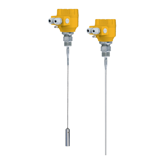
- Page 1 GF Piping Systems Instruction Manual 2291 Guided Radar Level Transmitter...
-
Page 3: Original Instruction Manual
Original instruction manual Follow the instruction manual The instruction manual is part of the product and is an important element of the safety concept. Read and follow the instruction manual. Always keep the instruction manual available of the product. ... -
Page 4: Table Of Contents
7.2.1 Installation instructions: General notes ................10 7.2.2 Specific installation instructions: Gauge – solid applications ...........13 Wiring ............................14 Power on and start-up ......................17 Programming type 2291 .......................18 The display unit ........................18 8.1.1 Behavior in manuals programming mode ................18 8.1.2 Manual programming......................19 Characteristics ........................20... -
Page 5: Intended Use
The device is applicable in tank, silo, rigid pipe, reaction vessel and level reference vessel. The device is HART capable; it can be programmed using the GF Signet configuration software Eview2 which is available on www.gfps.com/level Please note: All display units also can be programmed directly without any additional hardware. -
Page 6: Transport And Storage
Function Principle of operation The Type 2291 guided microwave level transmitter uses the TDR (Time Domain Reflectometry) principle. The instrument sends low power ns wide pulses along an electrically conductive rod, cable or coaxial probe with a known propagation speed (the speed of light). As the pulse... -
Page 7: Technical Data
Instruction manual Technical data Technical data Data Kv value Between the reference point of the unit and reflection Measured values plane (material surface), distance, level, and volume Input data Measuring range Single cable 6 m (19,7 ft), single rod 2 m (6.6 ft) Housing Plastic BPT Medium temperature... -
Page 8: Dimensions
Technical data Instruction manual Explosion Protection, Ex markings, Ex limit data Type Ex marking II 1 D iaD A20/21 IP 65 T100°C Intrinsically safe data Ci ≤ 10 nF, Li ≤ ≤ 30 V, Ii ≤ 150 mA, Pi ≤ 1 W For Ex transmitter only EEx ia power supply should be used Ex power supply... -
Page 9: Installation
Instruction manual Installation Installation Handling and Storage The device will weigh between approximately 1.5 kg or 3 lb, 12 kg or 25 lb. Carry using both hands to lift the device carefully by the converter housing. If necessary, use lifting gear. No attempt should be made to lift the instrument by its probe. Caution: The probe is a critical gauge component. -
Page 10: Mounting On The Tank
However, the gauge may be installed when the tank contains product. Threaded process connections The simplest and most economical way is to mount type 2291 directly on the tank with the 1” BSP or 1” NPT threaded connection. Nozzle height... - Page 11 Instruction manual Installation Installation of two devices If two devices are to be used on the same tank, these should be mounted at a distance of at least 2 m or 6.5 ft away from each other. If not, interferences from the electromagnetic (EM) fields generated by both instruments may cause measurement errors.
- Page 12 Installation Instruction manual Probes: entanglement, straightness and tank bottom clearance Cable probes must be straight once inserted into the tank. They must also be far from other objects (e.g. mixers) to avoid entanglement. In order to maintain the gauge’s operating characteristics, it is recommended to avoid touching the tank bottom with the counterweights (for cable probes) or probe...
-
Page 13: Specific Installation Instructions: Gauge - Solid Applications
Instruction manual Installation Fastening the probe to the tank bottom Flexible probes can be fastened with a chuck (ring), turnbuckle or similar fastening device to the tank bottom. Shortening cable probes If required, the cable probe can be shortened, but this applies only when used in liquids. Procedure 1. -
Page 14: Wiring
Installation Instruction manual Conical silo nozzles, false readings and traction on the cable probes 2. High traction forces: We recommend that the probe should not be anchored to avoid excessive traction loads on the cable. 3. Bending and traction: Position the connection on the roof at ½ radiuses of the tank and with minimum nozzle height. - Page 15 Connection to the EP network (grounding). Screw type terminal (EP) on the housing max. cable cross-section: 4 mm². The housing of the Type 2291 must be grounded. Grounding resistance R < 1 Ohm The shielding of the signal cable should be grounded at the control room.
- Page 16 RHART resistance for HART® communication 250 Ohm, recommended Line A = minimum voltage at the Type 2291 wire terminals Line B = minimum supply voltage (for voltage drop caused by a 250 Ohm loop resistance) Example for calculating the power supply: The voltage drop is tested at 22 mA:...
-
Page 17: Power On And Start-Up
IIB gas class hazardous area. Power on and start-up The Type 2291 wire is pre-configured in accordance to customer order specifications and measurements can be made immediately. A start-up time of less than 60 seconds should be allowed once the unit is connected and the power is switched on. -
Page 18: Programming Type 2291
Instruction manual Programming type 2291 The main parameters of the Type 2291 can be also set using the display unit. The default display shows the primary measured value (which the output current is calculated from).Besides the numerical display there is a bargraph on the right showing the value of the current output. -
Page 19: Manual Programming
Because manual programming (with display unit) and remote programming (with external HART master, or GF Signet Eview 2 software) cannot be performed at the same time (as both of them act like a HART master) only one programming mode has priority and this is manual programming. -
Page 20: Characteristics
Programming type 2291 Instruction manual Characteristics This subsection explains: the four principle configurations for setting up a measurement scale and what the user should be aware of in each case; what happens when the tank is full or empty;... -
Page 21: Gauge Operating Logic When The Reflection Is Lost
Instruction manual Programming type 2291 5. The “current output” range is greater than the measuring range: Scale min.: 4 mA = 0.0 Scale max.: 20 mA = tank height NOTE: The reference point for distance measurements is the bottom of the flange face. -
Page 22: Gain And Voltage Amplitude
Programming type 2291 Instruction manual 8.2.2 Gain and voltage amplitude As explained in the measuring principle in the introduction, the level of a product is converted from a return signal (the product reflection) received by the gauge: this signal has taken a... - Page 23 Instruction manual Programming type 2291 Amplification factor The amplitude of the signals is proportional to the dielectric constant r of the product. At low amplitudes the signal should be amplified. The amplification factor is dependent on the dielectric constant r and on the probe type. The device sets the gain automatically.
-
Page 24: Typical Signal Trends
Programming type 2291 Instruction manual In the diagram above it can be seen that the level of the threshold is not constant: 400 mV at 1000 mm or 3.3 ft, and only 250 mV at 10000 mm or 33 ft. No attenuation is required at a probe length ≤... -
Page 25: Automatic Adjustment
Instruction manual Programming type 2291 8.2.4 Automatic adjustment To maintain a sufficiently strong reflection signal, the gain is adjusted automatically. When the amplitude of the level reflection decreases, the gain will increase to compensate for the loss in signal amplitude. Gain and level threshold thus maintain the same proportion. - Page 26 Programming type 2291 Instruction manual Characteristics The level of the top product can be detected if it has a minimum layer of approximately 100 mm - when measuring a top product with a dielectric constant of r =2.4. The mode “2 liquids, 1 level” permits level to be measured even when more than 2 liquids are present in the tank.
-
Page 27: Troubleshooting
ESD and may need replacing. Please contact GF Piping Systems Contact GF Piping Systems for “Flange not found” The signal converter has been the corrective procedure. status marker on* incorrectly configured to measure with a cable or rod probe when it is equipped with a coaxial probe. - Page 28 HF board. “VC01 voltage error” * “VC02 voltage error” * “Reprogramming FPGA” * Gauge connected to GF Signet EView2 software. Event Fault Action General operation Instrument is not Tank height is not correct.
- Page 29 (see section 1.3.5). Ensure that no contact is possible. Contact GF Piping Systems for Instrument is not The instrument may be incorrectly the corrective procedure or accurate when there configured for this type of refer to the Service Manual.
-
Page 30: Repair And Maintenance
Instruction manual Repair and Maintenance Type 2291 does not require maintenance on a regular basis. In some very rare instances, however, the probe may need a cleaning from deposited material. This must be carried out gently, without damaging the probe. Repairs during or after the warranty period are carried out exclusively at the Manufacturers. - Page 32 GF Piping Systems Worldwide at home Our sales companies and representatives ensure local customer support in over 100 countries www.gfps.com Argentina / Southern South America France Mexico / Northern Latin America Singapore Georg Fischer Central Plastics Georg Fischer SAS Georg Fischer S.A. de C.V.
Need help?
Do you have a question about the 2291 and is the answer not in the manual?
Questions and answers