Advertisement
Quick Links
+GF+ SIGNET 8550-1 Flow Transmitter Instructions
3-8550.090-1
CAUTION!
•
Remove power to unit before wiring
input and output connections.
•
Follow instructions carefully to avoid
personal injury.
1. Installation
The transmitter is available in three versions: a panel mount version, an integral (pipe mount) version, and a universal assembly for
installation near the sensor.
1.1 Panel Installation
The Panel Mounting kits are supplied with the hardware to
install instrumentation into panels and maintain a NEMA 4X
seal.
1.
Punch out panel and de-burr edges. Recommended
clearance on all sides between instruments is 1 inch.
2.
Place gasket on instrument, and install in panel.
3.
Slide mounting bracket over back of instrument until
quick-clips snap into latches on side of instrument.
4.
Connect wires to terminals.
5.
To remove, secure instrument temporarily with tape from
front or grip from rear of instrument. DO NOT RELEASE.
Press quick-clips outward and remove.
1.2 Integral Assembly (3-8051)
1.
Punch out conduit ports if necessary.
2.
Connect sensor to integral adapter. Push and twist-lock
integral adapter to conduit base and secure with locking
ring and screw.
3.
Mount unit in pipe. Route cable through cable gland and
connect to transmitter.
4.
Close unit and secure. Seal cable entry.
1.3 Universal Assembly (3-8050)
1.
Install transmitter base
2.
Connect wires to transmitter.
3.
Close unit and secure with push and twist lock.
Seal cable entry.
2 . Specifications
General
Compatibility: +GF+ SIGNET Flow Sensors (w/freq out)
Accuracy: ±0.5 Hz
Enclosure:
•
Rating: NEMA 4X/IP65 front
•
Case: PBT
•
Window: Polyurethane coated polycarbonate
•
Keypad: Sealed 4-key silicone rubber
•
Weight: Approx. 325g (12 oz.)
Display:
•
Alphanumeric 2 x 16 LCD
•
Update rate: 1 second
•
Contrast: User selected, 5 levels
Environmental
Operating temperature: -10 to 70°C (14 to 158°F)
Storage temperature: -15 to 80°C (5 to 176°F)
Relative humidity: 0 to 95%, non-condensing
Standards and Approvals
•
CSA, CE, UL listed
•
Manufactured under ISO 9001
+GF+ SIGNET 8550-1 Flow Transmitter Instructions
A-9/99 English
Contents
1. Installation
2. Specifications
3. Electrical Connections
4. Menu Functions
Electrical
Sensor Input:
•
•
•
•
Current output:
•
•
•
•
•
Open-collector output: Hi, Lo, Frequency, Pulse Programmable
•
panel
gasket
latch
transmitter
cable
gland
wires
Range: 0.5 - 1500 Hz
2-wire: 1.5 mA @ 5 VDC ± 1%
Sensor power:
3 or 4 wire: 20 mA @ 5 VDC ± 1%
Optically isolated from current loop
Short circuit protected
4 to 20 mA, isolated, fully adjustable and reversible
Power: 12 to 24 VDC ±10%, regulated
Max loop impedance: 50 Ω max. @ 12 V, 325 Ω max. @ 18 V,
600 Ω max. @ 24V
Update rate: 100 ms
Accuracy: ±0.03 mA
Optically isolated, 50 mA
max. sink, 30 VDC max.
pull-up voltage.
ENGLISH
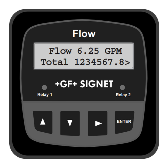
Flow
Flow 6.25 GPM
Total 1234567.8>
Relay 1
terminals
mounting
bracket
quick-clip
seal
seal
Internal open-collector
output circuit
15Ω
S
D
Isolation
page 1 of 6
Relay 2
ENTER
_
6
5
+
Advertisement

Related Manuals for GF SIGNET 8550-1


Summary of Contents for GF SIGNET 8550-1
- Page 1 ENGLISH +GF+ SIGNET 8550-1 Flow Transmitter Instructions 3-8550.090-1 A-9/99 English Flow CAUTION! Contents Flow 6.25 GPM Total 1234567.8> • Remove power to unit before wiring 1. Installation input and output connections. 2. Specifications Relay 1 Relay 2 • Follow instructions carefully to avoid 3.
-
Page 2: Electrical Connections
Terminals 1. AUX Power + 12-24 VDC 2. AUX Power - Note: AUX Power connections not required for +GF+ SIGNET flow sensors: 515, 525, 2536, 2517, 2540 (since Jan. 99), 8510-XX, 8512-XX, all Vortex frequency output sensors. System Power/Loop 3 (+) 12-24 VDC system power and current loop connections. - Page 3 Sys. Pwr. 4-20 mA in Loop + Channel 2 4-20 mA in * Note: Aux Power connections not required for +GF+ SIGNET Power - Channel 2 flow sensors: 515, 525, 2100, 2536, 2517, 2540 (since Jan. 99), 4-20 mA in...
-
Page 4: Menu Functions
Output Plswdth: 0.1 to 999.9 0.1 seconds 0.1 Seconds > seconds Frequency Selected Output Freq: 1 to 254 Divide by 1 > Last Cal: 00-00-00 to 01-01-99 01-01-99 > 39-39-99 +GF+ SIGNET 8550-1 Flow Transmitter Instructions page 4 of 6... -
Page 5: Troubleshooting
Troubleshooting Solution Problem Display Display timebase too large Change flow timebase —— (S=seconds,M=minutes,H=hours,D=days) in CALIBRATE menu to a smaller value (e.g. GPD to GPM Pulse width value too large for frequency Reduce output Plswidth setting or increase Output Volume Check settings input or pulse volume too small setting.
Need help?
Do you have a question about the SIGNET 8550-1 and is the answer not in the manual?
Questions and answers