Table of Contents
Advertisement
Quick Links
Advertisement
Table of Contents

Related Manuals for GF 2260


Summary of Contents for GF 2260
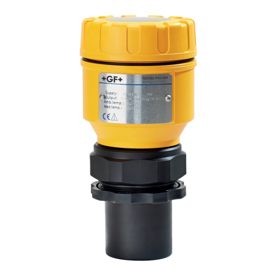
- Page 1 GF Piping Systems Instruction manual 2260 Ultrasonic Level Transmitter...
-
Page 2: Table Of Contents
Content 1. Safety and responsibility ..........................3 1.1 Intended use ............................... 3 1.2 Safety regulations for the Ex approved units .................... 3 2. Transport and storage ..........................3 3. Design and function ............................3 3.1 Design ................................. 3 3.2 Function ..............................4 3.3 Basic concepts and elements of the ultrasonic measurement............... - Page 3 Instruction for use Safety and responsibility 7. Parameters – Description and Programming ................... 22 7.1 Measurement configuration ........................22 7.2 Current output ............................26 7.3 Relay Output ............................. 27 7.4 Digital Output ............................28 7.5 Measurement optimisation ........................28 7.6 Volume Measurement ..........................31 7.7 Volume Flow Measuring ..........................
-
Page 4: Safety And Responsibility
1. Safety and responsibility 1.1 Intended use The 2260 Ultrasonic Level Transmitters are an excellent tool for the level measurement of liquids. Level measurement technology based on the non-contacting ultrasonic principle is especially suited for applications where, for any reason, no physical contact can be established to the surface of the material to be measured. -
Page 5: Function
2260 Ultrasonic Level Transmitter. A Total beam angle of 5°-7° at –3 dB as is featured by transducers of transmitters and sensores ensuring a reliable measurement in narrow silos with uneven side walls as well as in process tanks with various protruding objects. -
Page 6: Identification
Design and function Instruction for use Minimum measuring distance (X ) (Dead Band) is determined by the design of the unit within which the measurement is not possible (Dead Zone). This distance can be extended by programming in order to avoid disturbing effects of possible disturbing echoes coming from fixed objects. -
Page 7: Technical Data
Instruction for use Technical Data 4. Technical Data General Type 2260-X-XXX-4 2260-X-XXX-6 2260-X-XXX-15 Range 0.2 to 4 m / 0.65 to 0.25 to 6 m / 0.82 to 20 ft 0.45 to 15 m / 1.5 to 49 ft 13 ft * Total Beam Angle 6°... -
Page 8: Dimensions
Display Module 4.3 Maintenance and repair The 2260 Ultrasonic Level Transmitters do not require maintenance on a regular basis. In some very rare instances, however, the transducer may need a cleaning from deposited material. This must be carried out gently, without scratching or pressing the surface of the transducer. -
Page 9: Installation
Sensor alignment The sensor face has to be parallel to the surface of the liquid within ± 2-3°. Temperature Make sure that the 2260 Ultrasonic Level Transmitter will be protected against overheating by direct sunshine. Sonnenschirm Obstacles Make sure that no in-flow path or objects (e.g. cooling pipes, ladders, bracing members, thermometers, etc.) or no tank wall of... - Page 10 Installation Instruction for use Stand-off-Pipe The structure of the stand off pipe should be rigid; the inner rim where the ultrasonic beam leaves the pipe should be rounded. BSP/ NPT 1 ½” BSP/ NPT 2” Ø D Flange connection 130 mm 140 mm 150 mm 160 mm...
-
Page 11: Installation And Electrical Connection
Instruction for use Installation 5.2 Installation and electrical connection 5.2.1 Installation of the (BSP or NPT) threaded models Screw the unit in to its place. Use open wrench for tightening; max torque is 20Nm After tightening the enclosure can be rotated to the proper position. (Safety bolt prevents rotation more than 350°) ... -
Page 12: Details Electrical Connection
Damage due to supplying the terminals 1 and 2. Make sure that terminals 2 and 3 are supplied. Connection 4 -20 mA + test output Connection 4 – 20mA + HART For questions on HART Modem: Contact representative of GF Piping Systems. Connection internal relais... -
Page 13: Loop Current Checking
Instruction for use Installation Connection 9900 Universal Transmitter 5.3 Loop current checking After removing the cover and the Display Module the actual loop current can be measured with an accuracy of 0.5% by connecting an voltmeter (in the range of 200 mV) to the terminals indicated on the drawing above. -
Page 14: Programming In General
11 tanks with different shape and for 21 different open channels (flume, weir, etc). The devices are already equipped with the display module. The 2260 Ultrasonic Level Transmitter is fully operational without the display module. It is only needed for programming and/or displaying measurement values. -
Page 15: Procedure Of Programming
As a result of this setting the value of the analogue output will be 3.8 mA; 22 mA or according last value (hold) until the error is ceased. Action LED state following the action = 2260 Ultrasonic Level Transmitters in Press button steadily programming mode –... -
Page 16: Damping Time Setting
Instruction for use 6.1.5 Damping time setting (Check for a valid echo as above) Action LED state following the action = 2260 Ultrasonic Level Transmitter in Press ENTER button steadily programming mode – 10 sec Press any of the NEXT , UP = –... -
Page 17: Programming With The Display Module
6.2.5 QUICKSET Recommended as a simple and fast way to set up the 2260 Ultrasonic Level Transmitter, see „Quick Set Manual” at the beginning of this document. Qucikset by 6 basic parameters for the following basic settings, marked by abbreviations easy to remember: ... -
Page 18: Steps Of The Display Module
Programming in general Instruction for use Symbols used on the frame M – Metric system US – US calculation system LEDs lit COM – digital (Hart) communication VALID – presence of valid echo IrDA – Infrared communication port for logger readout, diagnostics and software upgrade. -
Page 19: Indications Of The Display Module And Led Status
Instruction for use Programming in general 6.2.3 Indications of the DISPLAY MODULE and LED Status LED indication VALID (ECHO)-LED lit in case of valid echo. COM-LED see description of HART RELAY-LED ON – when the ‘C2’ circuit of the relay is closed DISPLAY MODULE The following process values can be... -
Page 20: Quickset
(press for min 3 secs!) Increase/decrease and move left the blinking digit , DOWN , NEXT “GET LEVEL" - display actual level measured by the 2260 + DOWN Ultrasonic Level Transmitters Save readout and step to the next screen ENTER... -
Page 21: Full Parameter Access
(Empty). Description of failures can be found under the chapter „Error codes”. 6.2.5 Full parameter access Full Parameter Access is the highest programming level to access all features provided by the 2260 Ultrasonic Level Transmitters. Description of all parameters can be found under the chapter “Parameter”. - Page 22 Programming in general Instruction for use Steps and indications of the Full Parameter Access programming mode pressing Keys while Parameter Address is blinking while Parameter Value is blinking Save the modification of the Go to the Parameter Value Parameter Value and return to the ENTER Parameter Address Cancel all modifications of the actual...
-
Page 23: Parameters - Description And Programming
Instruction for use Parameters – Description and Programming 7. Parameters – Description and Programming 7.1 Measurement configuration P00: - cba Application/ Enginnering Units Programming of this parameter will result in loading the factory default with the corresponding engineering units. Operating (measurement) mode Liquid level measurement Engineering units (according to “c”) - Page 24 Parameters – Description and Programming Instruction for use P02: - cba Calculation units Attention: mind the sequence! Temperature When programming this parameter the right °C value “a” will be blinking first. °F This table is interpreted according to P00(c), P01(a) and P02(c) and is irrelevant in case of percentage measurement ( P01(a)= 2 or 4 ) Volume Weight (set also P32)
- Page 25 P04. To obtain the best accuracy, measure this distance in the empty tank with the 2260 Ultrasonic Level Transmitters by using the “GET LEVEL” function (by double key pressing of UP...
- Page 26 P05: Minimum measuring distance (Dead zone- Close-end blocking) The 2260 Ultrasonic Level Transmitters will not accept any echo within the blocking distance set here. Automatic Close-end-blocking (Automatic Dead Band control) By using the factory default value, the unit will automatically set the smallest possible close-end- blocking distance i.e.
-
Page 27: Current Output
- - - a Error indication by the current output In case of error the 2260 Ultrasonic Level Transmitter will provide one of the current outputs below. (For errors and their interpretation see Chapter 8). error indication (according to NAMUR) Hold last value 3.8 mA... -
Page 28: Relay Output
Parameters – Description and Programming Instruction for use 7.3 Relay Output P13: - - - a Relay function Relay function Also set P14, P15 DIFFERENTIAL LEVEL CONTROL (Hysteresis control) There is a need to Relay is energised if the measured or calculated value exceeds the value set (in level min set in P14 Relay is de-energised if the measured or calculated value 20mm) hysteresis... -
Page 29: Digital Output
This parameter can be used to reduce disturbing effect of possible multiple echos.. Compensation Applied In case the 2260 Ultrasonic Level Transmitters is not mounted in the centre of the top and the top is flat. In case the 2260 Ultrasonic Level Transmitters is mounted... - Page 30 Parameters – Description and Programming Instruction for use P25: - - - a Selection of Echo within the measuring window A so-called measuring window is formed around the echo signal. The position of this measuring window determines the flight time for calculation of the distance to the target. (the picture below can be seen on the test oscilloscope) Received Echo 2.
- Page 31 Instruction for use Parameters – Description and Programming P28: - - - a Echo loss indication Echo loss Remark indication During echo-loss, display and analogue output will hold last value. If the echo-loss prevails for 10 sec plus the time period set in P20 (damping time), the reading on the display will change to "no Echo"...
-
Page 32: Volume Measurement
Parameters – Description and Programming Instruction for use P29: Blocking out of disturbing object One fixed object in the tank, disturbing the measurement, can be blocked out. Enter distance of the object from the transducer. Use the Echo Map (P70) to read out the precise distance of disturbing objects. -
Page 33: Volume Flow Measuring
Instruction for use Parameters – Description and Programming Lying cylindrical tank Spherical tank 7.7 Volume Flow Measuring 7.7.1 Open Channel Flow Measurement For ultimate accuracy, install the sensor as close as possible above the expected maximum water level (see minimum measuring range). ... - Page 34 Parameters – Description and Programming Instruction for use Devices, formula, data Also to be set Suppressed rectangular or BAZIN weir P46, P41, P42 Trapezoidal weir P46, P41, P42 Special trapezoidal (4:1) weir P46, P42 V-notch weir P46, P42 THOMSON (90°-notch) weir Circular weir P46, P41 General flow formula: Q[l/s]= 1000*P41*h...
- Page 35 Instruction for use Parameters – Description and Programming P40= Palmer-Bowlus (D/3) flume /s]= f(h1/P41)*P41 where h1[m]= h+(P41/10) D/10 P40= Palmer-Bowlus (Rectangular) flume /s]= C*P42*h where C= f(P41/P42) D/10 15cm P40= Khafagi Venturi flume /s]= P42*1.744*h + 0.091*h Sensor Sensor P40=14 P40= Bottom step weir 0.0005 <...
-
Page 36: 32-Point-Linearisation
Parameters – Description and Programming Instruction for use P40=17 P40= Special Trapezoidal (4:1) weir 0.0018 < Q[m3/s] < 50 0.3 < P42[m] < 10 0.1 < h[m] < 2 Q[m3/s]= 1.866*P42*h Accuracy: 3% P40=18 P40= V-notch weir 0.0002 < Q[m3/s] < 1 20 <... - Page 37 32 data-pairs j<32, the table must be closed by a level value “0” e.g. L(j<32)= 0. The 2260 Ultrasonic Level Transmitters will ignore data after recognising level value “0” with serial number other than “1”.
-
Page 38: Informational Parameters (Read Out Parameters)
(see Chapter „Error codes”). The transmitter will perform temperature correction corresponding to 20ºC. P70: Number of Echoes / Echo Map 2260 Ultrasonic Level Transmitters is monitoring the echo conditions.Entering this parameter will save the actual echo map. Number, distance and amplitude of these echoes can be read- out one by one. -
Page 39: Additional Parameters Of The Flow Metering
Instruction for use Parameters – Description and Programming P74: Signal To Noise Ratio Ratio Measurement conditions Over 70 Excellent Between 70 and 30 Good Under 30 Unreliable P75: Blocking Distance The actual close-end blocking distance will be displayed (provided automatic blocking was selected in P05. -
Page 40: Simulation
Instruction for use 7.12 Simulation This function enables the user to test the settings of the outputs. The 2260 Ultrasonic Level Transmitters can simulate the static or continuous change of level according to the simulation cycle time, high level and low level set in P85, P86 and P87. (The simulation levels must be within the programmed measuring range set in P04 and P05.) -
Page 41: Error Codes
Error Codes 8. Error Codes Error Error description Causes and solutions Code Memory error Contact representative of GF Piping Systems No echo received (no reflection), see chapter kein Echo loss „Indication of mistakes (by LEDs) made during Echo programming” Hardware error... -
Page 42: Parameter Table
Parameter table Instruction for use 9. Parameter table Par. Page Description Value Par. Page Description Value d c b a d c b a P00 22 Application/Engineering Echo loss indication Units P01 22 Measurement Mode Blocking out of disturbing object P02 22 Calculation units N.A. - Page 43 Instruction for use Parameter table Par. Page Description Value Par. Page Description Value d c b a d c b a N.A. TOT2 volume flow totaliser N.A. N.A. N.A. Current generator test N.A. Relay test P60 37 Overall operating hours N.A.
-
Page 44: Sound Velocities In Different Gases
Range 4 m, PVDF body, 4..20 mA 2-wire / HART, ATEX, BSP thread 159 300 113 2260-V-1DBX-6 Range 6 m, PVDF body, 4..20 mA 2-wire / HART, ATEX, BSP thread 159 300 114 2260-V-1DFX-15 Range 15 m, PVDF body, 4..20 mA 2-wire / HART, ATEX, DIN Flange DN125 159 300 120 2260-P-0DN-4 Range 4 m, PP body, 4..20 mA 2-wire, NPT thread... -
Page 45: Disposal
Range 4 m, PVDF body, 4..20 mA 2-wire / HART, ATEX, NPT thread 159 300 143 2260-V-1DNX-6 Range 6 m, PVDF body, 4..20 mA 2-wire / HART, ATEX, NPT thread 159 300 144 2260-V-1DAX-15 Range 15 m, PVDF body, 4..20 mA 2-wire / HART, ATEX, ANSI Flange 5 inch 12. Disposal ... - Page 46 ...
- Page 47 ...
- Page 48 GF Piping Systems Worldwide at home Our sales companies and representatives ensure local customer support in over 100 countries www.gfps.com Argentina / Southern South America France Netherlands Switzerland Georg Fischer Central Plastics Georg Fischer SAS Georg Fischer N.V. Georg Fischer Sudamérica S.R.L.
Need help?
Do you have a question about the 2260 and is the answer not in the manual?
Questions and answers