GF Signet 9950 Operating Instructions Manual
Dual channel transmitter
Hide thumbs
Also See for Signet 9950:
- Instruction sheet (2 pages) ,
- Instruction sheet (2 pages) ,
- Operating instructions manual (13 pages)
Table of Contents
Advertisement
Signet 9950 Dual Channel Transmitter
*3-9950.090*
3-9950.090 Rev. C 05/17
3-9950-1, -2
NOTE:
Prior to installation, Check
www.gfsignet.com
software updates to your
device. See page 48, Field
Software Update, for more
information.
Description
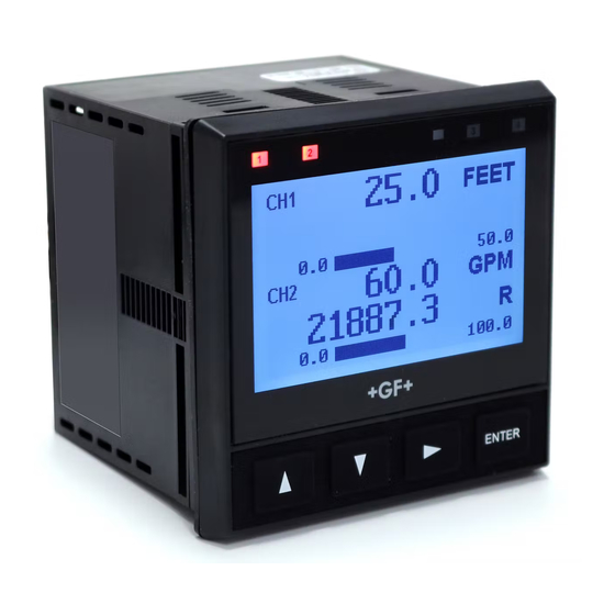
The 9950 Dual Channel Transmitter is a two channel controller that can support
two sensors of same or different types in one instrument. The sensor types
supported by the 9950 are Signet Flow, pH/ORP, Conductivity/Resistivity, Salinity,
Temperature, Pressure, Level, Dissolved Oxygen, and devices that transmit a
4 to 20 mA signal with the use of the 8058 iGo
The 9950 includes advanced features such as derived functions, advanced
multiple relay modes, and timer based relay functions. Derived functions allows
for the control of a relay or current loop with the sum, delta (difference), or ratio
of two measurements. Multiple relay modes allow up to three signals to be used
for the control of a single relay, and can be any combination of analog and binary
inputs. The timer relay modes allow a relay to be activated on a repeating basis
from every minute to once every 30 days. Weekday timer mode allows a relay to
be energized, on a specifi c day or days of the week at a specifi c time.
The 9950 supports the following relay modules:
•
Four Channel Mechanical Relay Module
•
Two Mechanical and Two Solid State Relay Module
•
Two Mechanical Relays and Four Binary Inputs Module
for
Compatibility
The 9950 is compatible with all GF Signet
products listed in the column to the right.
● pH and ORP electrodes require the
Signet 2750 or 2751 DryLoc
Electronics (sold separately).
● Conductivity/Resistivity
measurement requires the Signet
2850 Conductivity/Resistivity Sensor
Electronics (sold separately).
•
English
•
Deutsch
•
Español
•
中文
Operating Instructions (see pg. 10)
®
Signal Converter.
Sensor
Model
515/8510
525
2000
2100
2250
2350
®
Sensor
2450
2507
2536/8512
2537-5
2540
2551
2552
U1000
U3000
U4000
2260
2270
2290
2291
2610-41
2724-2726
2734-2736
2750/2751
2756-2757
2764-2767
2774-2777
2819-2823
2839-2842
2850
English
Freq
Digital (S
L)
Requires
3
Output
Output
8058
X
X
X
X
X
X
X
X
X
X
X
X
X
X
X
X
X
X
X
X
X
X
X
X
X
X
X
X
X
X
X
X
X
X
X
Advertisement
Table of Contents

Subscribe to Our Youtube Channel
Related Manuals for GF Signet 9950


Summary of Contents for GF Signet 9950
- Page 1 Software Update, for more Model Output Output 8058 information. 515/8510 The 9950 is compatible with all GF Signet 2000 products listed in the column to the right. 2100 2250 ● pH and ORP electrodes require the 2350 Signet 2750 or 2751 DryLoc ®...
- Page 2 Start-Up Guide Safety Information Warning / Caution / Danger Indicates a potential hazard. Failure to follow all warnings may lead to equipment damage, injury, or death. • Please read entire manual before unpacking, setting up or operating this equipment. Adhere to all danger, warning Electrostatic Discharge (ESD) / Electrocution Danger and caution statements.
-
Page 3: Terminal Identifi Cation
Start-Up Guide Terminal Identifi cation Prepare the transmitter installation location. If the back of the transmitter is diffi cult to access when installed, wire the removable terminal blocks fi rst, then install it completely. DC Power Terminals Current Loop Outputs MODULE 1 11-24 VDC RELAY MODULE... -
Page 4: Sensor Wiring
Start-Up Guide Sensor Wiring 9950 Frequency Technical Notes: • See corresponding product manuals for maximum 515/8510 2536/8512 2540 DC POWER cable length. FLOW • Maintain cable shield through cable splice. • Route sensor cable away from AC power lines. Loop Loop •... - Page 5 Start-Up Guide Sensor Wiring 2551-XX-11 Blind Magmeter 9950 S L Inputs 9950 Frequency DC POWER DC POWER Frequency PWR+ PWR+ PWR– PWR– Loop1+ Loop1+ 2551 Technical Notes: Loop1– Loop1– • When the blue jumper Loop2+ Loop2+ illustrated here is placed Loop2–...
-
Page 6: Power Wiring
Start-Up Guide Power Wiring WARNING DO NOT connect AC power to the DC version THE 3-9950-1 MUST BE POWERED BY 12 - 32 VDC at 0.5 A. 3-9950-1 and 3-9950-2 DC POWER PWR+ Power Supply – 12 to 32 VDC PWR–... -
Page 7: Relay Module Wiring
Start-Up Guide Relay Module Wiring • Terminals accept 12 to 24 AWG wire. • Strip 10 to 12 mm (0.4 to 0.5 in.) of insulation from wire tips and tin bare ends to eliminate fraying. • Insert wire tip or ferrule completely into the terminal and secure with the screw. •... -
Page 8: Operation
Start-Up Guide Operation Keypad Functions The four buttons of the keypad (▲ ▼ ► ENTER) are used to navigate display modes according to the descriptions in this table. Notice the function of each button may change depending on the display mode. This menu operation sets up the 9950 for basic function: Select desired language using the [UP] and [DOWN] arrows. -
Page 9: Password
Start-Up Guide Password Password Overview The password is required to start editing. Once entered correctly, this password will not be needed for subsequent uses, until the menu system is exited. The password will be required when the menu system is re-entered. Your choice of password (STD or CODE) is selected in the Options Mode. -
Page 10: Table Of Contents
All warranty and non-warranty repairs being returned Wiring ................4 must include a fully completed Service Form and Sensor Wiring .............4 goods must be returned to your local GF Sales offi ce or Sensor Wiring .............5 distributor. Power Wiring ..............6 Product returned without a Service Form may not be Relay Module Wiring ..........7... -
Page 11: Dimensions
Dimensions Module Installation 3-9950-1/-2 Front View 99.06 mm (3.90 in.) 99.06 mm (3.90 in.) CAUTION Avoid Electrostatic Discharge (ESD). ENTER The plug-in modules may be installed either before or after the base unit is mounted. If the 9950 Base Unit will be mounted using the provided quick clip mounting bracket. -
Page 12: Plug-In Modules
Plug-In Modules Optional modules and accessories are available for the 9950: a. Base Unit (required) b. Slot for optional Relay Module c. Slot for optional Module 1 d. Slot for optional Module 2 Each item is ordered separately. Modules are fi eld-replaceable at any time. See Module Installation (pg. -
Page 13: Signal Type: Frequency
Signal Type: Frequency Signet fl ow sensors 515/8510, 525, 2000, 2100, 2507, 2536/8512 and 2540 provide a Maximum Flow sensor frequency output. (Flow sensors 2537, 2551 and 2552 can be confi gured with either Cable Length models with Digital (S L) or Frequency outputs). -
Page 14: Signal Type: 4 To 20 Ma
In the 9950 INPUT menu, sensor TYPE screen, select the '4 to 20 INPUT' sensor (see System Setup Menu discussion, page 8). 9950 S L Inputs 8058-1 8058-1 DC POWER PWR+ +GF+ Signet 8058 i-Go™ 4-20 mA to S L Converter PWR– 4-20 mA input L Output Loop1+ Loop1–... -
Page 15: Relay Modes
Relay Modes Generation II, or greater, supports the ability to activate the The 9950 relays are selectable and confi gurable and can be Red Backlight when a relay is activated. An optional check used as switches that respond when the process value moves box is displayed during the programming of a relay that will above or below a user-defi... - Page 16 Relay Modes Window In/Out: Process Relay is on when the value is equal to or higher or lower than the high or low setpoint. Hysteresis High Limit WINDow IN = relay on if measurement is inside the window Window of two setpoints. Low Limit Hysteresis WINDow OUT = relay on if measurement is outside the...
- Page 17 Relay Modes • Pulse Width Modulation Maximum PWM automatically varies the ratio of ON time to OFF time Range proportional to minimum and maximum range settings. 100% Relay is The relay period is the sum of the time a relay is ON and the always ON time it is OFF.
- Page 18 Relay Modes • Multiple When a Relay Source is set to "MULTIPLE," the mode presents four Boolean logic formulae called "Relay Operators." Each Operator can be programmed with up to three different conditions. The relay will only be activated when the complete formula is satisfi...
-
Page 19: Derived Functions
Derived Functions When two of the same type of measurement are present, the 9950 can calculate several derived functions from like pairs of measurements. Up to four derived Functions can be defi ned and used as the source for display and output functions. •... -
Page 20: Menu System
Menu System VIEW Mode Overview The top level of screens are referred to as the VIEW Mode. This view displays measurement Error Handling values as well as current outputs, derived function values, and relay status. The horizontal bar Errors occurring while on the graph represents the primary measurement value that is also displayed in the numeric fi... -
Page 21: Common Menu
Common Menus Common Menus NOTE: The menu system shares certain modes between sensor Menu and Mode displays shown are examples only. types. Your displays may vary. The following describes the menus found in common between most sensor types. INPUT Menu INPUT INPUT LOOP... -
Page 22: Relay Menu
Common Menus RELAY Menu All relays select source for each Relay 1 - 4. Choose CH 1 PRIMARY, CH 1 SECONDARY, CH 2 PRIMARY, RELAY 1 CH 2 SECONDARY, BINARY 1 - 4, DERIVED FUNCTION 1 - 4, TIMER, or MULTIPLE. Secondary Values are SOURCE only available for pH, Conductivity/Resistivity, Level, Salinity and Dissolved Oxygen. - Page 23 Common Menus RELAY Menu R1 SET HIGH (ALL) (Shown if HIGH, CYCLE HIGH (all except Flow) or WIND IN/OUT mode) 100.0 Relay energizes if process measurement is equal to or higher than this value. Set desired value. mUNITSA R1 SET VOLUME (FLOW only) (Shown if Cycle High (Flow), TOTAL or VOL PLS mode) Amount of accumulated fl...
-
Page 24: Option Menu
Common Menus RELAY Menu R1 PULSE WIDTH (FLOW only) (Shown only if VOL PULS mode) Set time value for one pulse width. 1.00 R1 SET TOTAL (FLOW only) (Shown only if TOTAL) Resettable value that, when exceeded, turns relay on. 100.00 Must reset Totalizer (in VIEW Mode) to clear relay. - Page 25 Common Menus OPTION Menu WHITE BACKLIGHT White Backlight; Off, Low, High, Auto Low, Auto High AUTO LOW RED BACKLIGHT The Red Backlight illuminates when an error condition is detected; Default is ON DISPLAY Display Bar Graph; On, Off BAR GRAPH CH2 BAR GRAPH MIN Enter a value to represent bar at minimum.
-
Page 26: View Mode
Common Menus OPTION Menu MEMO (ALL) Enter 17-character string, if desired. MEMO Default = MEMO 9950 Displays Transmitter Generation Version. GENERATION 2a USER MANUAL QR code for user manual. 100.00 Measurement View Mode Screens are depicted in the Sensor Specifi c Menus. Below are the screens VIEW Mode that all parameters share in common. - Page 27 Common Menus VIEW Mode SYS CONFIG FLOW FLOW SYS CONFIG shows channel and parameter and relay module part number. RELAY 399504033 MOD1 4-20 OUT GENERATION I SW VER 00-20 DBG Generation Screen shows version of software and serial number of unit. 9950 S/N 0123456789 Note: Top shows the Generation of 9950...
-
Page 28: Sensor-Specifi C Menus
Sensor-Specifi c Menus The following pages list the sensor-specifi c settings for each sensor type. The user can confi gure the Flow unit to run each channel on different parameters if needed. VIEW Mode Menu 50.30 FLOW Setup Checklist 1. Make sure FLOW sensor type is selected 40560.0 (see System Setup Menu, page 8). - Page 29 Flow INPUT Menu CHANNEL 1 If desired, a custom name can be entered. Enter 17-character string. NAME Default = FLOW FLOW CH 1 FLOW If your fl ow sensor is confi gured for frequency output, select FREQ. If confi gured for Digital (S L) output (recommended), select S MODE Default = FREQ.
- Page 30 VIEW Mode Menu pH Setup Checklist 1. Make sure pH sensor type is selected 77.0 (see System Setup Menu, page 8). °F 2. Set the Temperature Units (°C or °F). -1.00 15.00 3. If LOOP is used, set the minimum and maximum 4 to 20 mA setpoints. 4.
- Page 31 CAL Menu CH 2 pH ON prevents relays from activating while making adjustments and relays in PULSE mode will suspend pulsing. 4 to 20 mA output is held until the user exits the CAL menu or turns it OFF. Select ON/OFF. Default = OFF. HOLD OUTPUTS CH 2 pH Select AT SENSOR to perform calibration using the Signet 2750 sensor electronics.
- Page 32 INPUT Menu CHANNEL 2 If desired, a custom name can be entered. Enter 17-character string. NAME Default = pH CH 2 pH Select °F or °C. °F Default = Determined by the SELECT UNITS screen menu. Metric = °C, U.S. Customary = °F. AT INSTRUMENT CH 2 pH Dampens display, output and relay response rates.
-
Page 33: Orp
VIEW Mode Menu 84.0 ORP Setup Checklist 1. Make sure ORP sensor type is selected (see System Setup Menu, page 8). CUSTOM LABEL 2. If LOOP is used, set the minimum and maximum 4 to 20 mA setpoints. -999.0 1000.0 3. - Page 34 CAL Menu CH 2 ORP ON prevents relays from activating while making adjustments and relays in PULSE mode will suspend pulsing. Output is held until the user exits the CAL menu or turns it OFF. Select ON/OFF. Default = OFF HOLD OUTPUTS CH 2 ORP Select AT SENSOR to perform calibration using the Signet 2750 sensor electronics.
-
Page 35: Conductivity/Resistivity
Conductivity / Resistivity VIEW Mode Menu Cond/Res Setup Checklist 1205.00 1. Make sure COND/RES sensor type is selected 77.0 (see System Setup Menu, page 8). °F 2. Set Cell Constant. 100.00 0.0000 3. Set the Temperature Units (°C or °F). 987.9 4. - Page 36 Conductivity / Resistivity INPUT Menu CHANNEL 2 If desired, a custom name can be entered. Enter 17-character string. NAME Default = COND/RES COND/RES CH 2 COND/RES Enter cell constant of sensor. Select 20.0, 10.0, 1.0, 0.1, 0.01, or CUSTOM. SENSOR 1.0 Default = 1.0 (See NOTE below) CELL CONSTANT CH 2 COND/RES...
-
Page 37: Pressure
Pressure VIEW Mode Menu PRESSURE Setup Checklist 1. Make sure PRESSURE sensor type is selected (see System Setup Menu, page 8). 77.0 °F 2. If LOOP is used, set the minimum and maximum 4 to 20 mA setpoints. 10.0 3. Set Units of Measurement (PSI, BAR, KPa). 4. - Page 38 Pressure INPUT Menu CHANNEL 2 If desired, a custom name can be entered. Enter 17-character string. NAME Default = PRESSURE PRESSURE CH 2 PRESSURE Enter units of pressure measurement. Select PSI, BAR, or KPa. Default = Determined by the SELECT UNITS screen menu. Metric = Bar, U.S. Customary = PSI. PRESS UNITS CH 2 PRESSURE Dampens display, output and relay response rates.
-
Page 39: Level/Volume
Level / Volume VIEW Mode Menu 25.0 LEVEL/VOLUME Setup Checklist 1. Make sure LEVEL/VOLUME sensor type is selected 78.5 (see System Setup Menu, page 8). 2. Select Main Measurement (Level or Volume). 10.000 0.0000 3. Set Units of Measurement for LEVEL display (FT, IN, M, CM). 20.0 4. - Page 40 Level / Volume INPUT Menu CH 2 LEVEL Select unit of measure for LEVEL display (FT, IN, M, CM). Default = Determined by the SELECT UNITS screen menu. Metric = M, U.S. Customary = FT. LEVEL UNITSL CH 2 LEVEL ON = Measurement will be displayed as a percentage of full scale.
- Page 41 Level / Volume INPUT Menu Set length of tank. 10.00 Default = 10.00 TANK LENGTH Set width of tank 10.0 Default = 10.00 TANK WIDTH CH 2 LEVEL If Custom shape is selected, enter the number of measurement points to be used to defi ne the vessel shape (see Level and Volume Calculation in Custom Shaped Vessels discussion, page 52).
-
Page 42: Temperature
Temperature VIEW Mode Menu 113.0 TEMPERATURE Setup Checklist °F 1. Make sure TEMPERATURE sensor type is selected 9999.9 (see System Setup Menu, page 8). GPMS 2. If LOOP is used, set the minimum and maximum 4 to 20 mA setpoints. 100.00 0.00 3. -
Page 43: To 20 Ma
4 to 20 mA VIEW Mode Menu 4 to 20 mA Setup Checklist 50.0 UNIT 1. Make sure 4 to 20 mA INPUT sensor type is selected (see System Setup Menu, page 8). 2. Set 4 mA value (refer to your 3rd-party sensor manual). CUSTOM LABEL 3. - Page 44 4 to 20 mA INPUT Menu CHANNEL 2 If desired, a custom name can be entered. Enter 17-character string. AVNAMEFE°° Default = 4-20 mA 4-20mA INPUT CH2 4-20mA INPUT Enter up to 4 characters describing unit of measure. UNIT Default = UNIT. SENSOR UNITS CH2 4-20 mA INPUT Measurement value of your sensor when its output is 4.00 mA.
-
Page 45: Salinity
Salinity VIEW Mode Menu 81.9 Setup Checklist 1. Make sure SALINITY sensor type is selected (see System Setup Menu, page 8). °F 2. Set Cell Constant. 0.0000 80.000 3. Set the Temperature Units (°C or °F). 85.9 4. If LOOP is used, set the minimum and maximum 4 to 20 mA setpoints. 5. - Page 46 Salinity INPUT Menu CHANNEL 2 If desired, a custom name can be entered. Enter 17-character string. NAME Default = SALINITY SALINITY CH 2 SALINITY Enter cell constant of sensor. Select 20.0, 10.0, 1.0 or CUSTOM. 20.0 Default = 20. CCELL CONSTANT CH 2 DO Enter the precise cell constant from the certifi...
-
Page 47: Dissolved Oxygen
Dissolved Oxygen VIEW Mode Menu DISSOLVED OXYGEN Setup Checklist (3-2610-41) 2610 wiring on page 4. 20.0 1. Make sure DISSOLVED OXYGEN sensor type is selected °C (see System Setup Menu, page 8). 0.00 20.00 10.9 2. Set Units of Measurement (PPM, %SAT, TOR). 3. - Page 48 Dissolved Oxygen INPUT Menu CH2 DO If desired, a custom name can be entered. Enter 17-character string. AVENAMEAGE Default = DO CH2 DO Set the units of measurement: PPM = DO in mg/L; %SAT = DO % saturation; TOR = Oxygen partial pressure. Default = PPM. MEASUREMENT CH2 DO Manually set value to match application (0 - 42 PSU).
-
Page 49: Updating The 9950
9950 Field Software Upgrade The 9950 upgrade fi le will be available on the Georg Fischer website. You will need a USB fl ash drive that is formatted, using Microsoft Windows, in either FAT16 or FAT32 format. Do not use exFAT or NTSF formats. -
Page 50: Troubleshooting
Troubleshooting Condition Possible Causes Suggested Solution Incorrect sensor installed on channel Connect correct sensor to channel Wrong Sensor Set correct sensor TYPE in INPUT menu Sensor Type set incorrectly in 9950 (see page 8) Wrong Code Wrong password entered Enter correct password (see page 20) K-Factor Out Of Range K-Factors cannot be set to 0 Enter K-Factor from 0.0001 to 99999... - Page 51 Troubleshooting Condition Possible Causes Suggested Solution 9950 "cannot communicate" to sensor No Probe • Check wiring Missing sensor or bad temperature (pH/ORP only) • Install or replace sensor element. No Sensor • Check wiring (Flow, Cond/Res, Press, 9950 "cannot communicate" to sensor Level, Temp, 4-20 mA, •...
-
Page 52: Appendix
Appendix Averaging O AVERAGING, NO SENSITIVITY With SENSITIVITY set to 0 (zero) and AVERAGING set to OFF (0 seconds), the 9950 responds immediately to every shift in the process. The dashed red line represents the actual output of the sensor in varying conditions. AVERAGING ONLY With SENSITIVITY still set to zero and AVERAGING set to MED or HIGH the rate is stabilized, but a sharp change in rate is not represented for 8 to 32 seconds or longer. -
Page 53: Custom Measurements
Appendix Custom Measurements Defi ning a Custom Tank Determine where the level measurement should start. This is the zero reference point (Z). Review the diagram to help select the best option. Determine where you will mount the sensor. This is S . - Page 54 Appendix Custom Measurements Level and Volume Calculation in Custom Shaped Vessels In the LEVEL/VOLUME menu, if Custom Shape is selected in the INPUT menu, you can defi ne from three to ten Custom Points to establish the relationship of level to volume in the vessel. •...
- Page 55 Appendix Custom Measurements In the LEVEL/VOLUME INPUT menu (see page 40), if SHAPE is set to HORIZ CYLINDER, RECTANGLE or CUSTOM, the tank shape can be defi ned with the following screens: CH 2 LEVEL If Custom shape is selected, enter the number of measurement points to be used to defi ne the vessel shape (see Level and Volume Calculation in Custom Shaped Vessels discussion, page 52).
- Page 56 Appendix Custom Measurements Pressure to level conversion: Level = P ÷ (SG × D) Technical Reference for where P = Pressure Level, Volume, and Mass Measurement SG = Specifi c Gravity of fl uid = Density of water The 9950 can automatically perform level, volume and mass calculations: With pressure in psi: Level (meters) = 0.703069 ×...
-
Page 57: Calibration Procedures - Ph
Appendix Calibration Procedures - pH EasyCal Procedure - pH EasyCal is the fastest and simplest periodic calibration method. Requires prepared 4, 7 or 10 pH buffers (any two). • This procedure simplifi es To Calibrate: Response: To Accept: pH calibration using standard 4.0, 7.0, 10.0 pH PLACE SENSOR CH pH... -
Page 58: Calibration Procedure - Orp
Appendix Calibration Procedures - pH Manual Calibration Procedure - pH Requires prepared buffers. System calibration is possible with two known pH solutions within 0 to 14 pH (buffers of pH 4.01, 7, or 10 are recommended, but use a buffer close to your own process value.) Single-point calibration sets To Set Standard: To Change Reading:... - Page 59 Appendix Calibration Procedures - ORP EasyCal Procedure - ORP (one-point calibration) EasyCal is the fastest and simplest periodic calibration method. Requires a prepared quinhydrone solution or Light's Solution: Saturate 50 mL of pH 7 (87 mV) or pH 4 (264 mV) buffers with 1/8 g quinhydrone. Premixed Light's Solution (476 mV) can be used instead of pH buffers with quinhydrone.
- Page 60 Appendix Calibration Procedures - ORP Manual Calibration Procedure - ORP Requires prepared buffers and a prepared quinhydrone solution: Saturate 50 mL of pH 4 and 7 buffers with 1/8 g quinhydrone. (System calibration is possible with two known ORP solutions, but use a buffer close to your own process value).
-
Page 61: Calibration Procedure - Conductivity/Resistivity
Appendix Calibration Procedures - Conductivity / Resistivity Calibration Procedure - Conductivity/Resistivity AutoCal is the fastest and simplest periodic calibration method. Requires prepared buffer of a value appropriate to your process. AutoCal Procedure Conductivity units are displayed as selected in AutoCal is a single-point calibration system. During this procedure, if the measured the CALIBRATE menu. -
Page 62: Calibration Procedure - Flow
Appendix Calibration Procedures - Flow Calibration Procedure - Flow Select RATE CALIBRATION to match the dynamic fl ow rate to an external reference. Entering a rate will modify the existing K-Factor. Select VOLUME CALIBRATION if the fl ow rate can be determined by fi lling a vessel of known volume. The 9950 will count the number of pulses generated as the known volume of fl... -
Page 63: Calibration Error Messages
Appendix Calibration Error Messages Message Cause Solution Cond/Res ) Error > 10% in AutoCal Use manual calibration method (pH) Buffer not found; Use 4, & 7 pH buffers (with quinhydrone Out Of Range Use Manual Error > ±1.5 pH units for ORP calibration) or Light's Solution Calibration Clean sensor and retry EasyCal... -
Page 64: Usp Limits
Appendix USP Limits USP (United States Pharmacopeia) has defi ned a set of conductivity values (limits) to be used for pharmaceutical water. The standard requires that conductivity Temperature USP limit measurement without temperature compensation be used for these applications. Range (ºC) (μS) The limits vary according to the temperature of the sample. -
Page 65: Map Of 9950 Relay And Loop Sources
Appendix Map of 9950 Relay and Loop Sources Measurement Loop and Relay Control Parameters Loop n Param. Frequency Loop n Source 4 mA Setpoint Flow Loop and Relay 20 mA Setpoint None Input Input Sources Loop n Mode Terminal CH 1 Pri/Sec Error Value Block 1 CH 2 Pri/Sec... -
Page 66: Specifi Cations
Specifi cations General Electrical Requirements Input channels ....Two channels, programmable for Power to Sensors Digital (S L) or frequency input Voltage....... +4.9 to 5.5 VDC @ 25 °C, regulated Outputs.......Two passive 4 to 20 mA loop outputs Current....... 30 mA Maximum standard Two or four programmable relay Short Circuit .......Protected... - Page 67 Specifi cations Relay Specifi cations Binary Input Specifi cations (3-9950.393-3) Input voltage range Dry-Contact Relays (without damage) ....-5 VDC to 30 VDC Type ........SPDT (no operation below 0 VDC) Form ........C Max. Voltage Rating ..... 30 VDC or 250 VAC Max.
-
Page 68: Ordering Information
Ordering Information 9950 Transmitter Base Unit: Dual Channel, Multi-Parameter, AC Power and DC Power Mfr. Part No Code Description 9950 Base Unit – Two Channel Multi-Parameter Inputs, Two 4 to 20 mA 3-9950-1 159 001 841 Outputs, Panel Mount, DC Power 9950 Base Unit –...
Need help?
Do you have a question about the Signet 9950 and is the answer not in the manual?
Questions and answers