Advertisement
Quick Links
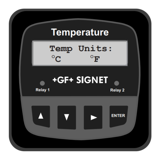
+GF+ SIGNET 8350-3 Temperature Transmitter Instructions
3-8350.090-3
CAUTION!
•
Remove power to unit before wiring
input and output connections.
•
Follow instructions carefully to avoid
personal injury.
1. Installation
The transmitter is available in three versions: a panel mount version, an integral (pipe mount) version, and a universal assembly for
installation near the sensor.
1.1 Panel Installation
The Panel Mounting kits are supplied with the hardware to
install instrumentation into panels and maintain a NEMA 4X
watertight seal.
1.
Punch out panel and de-burr edges. Recommended
clearance on all sides between instruments is 1 inch.
2.
Place gasket on instrument, and install in panel.
3.
Slide mounting bracket over back of instrument until
quick-clips snap into latches on side of instrument.
4.
Connect wires to terminals.
5.
To remove, secure instrument temporarily with tape from
front or grip from rear of instrument. DO NOT RELEASE.
Press quick-clips outward and remove.
1.2 Integral Assembly (3-8052)
1.
Punch out conduit ports if necessary.
2.
Connect sensor to integral adapter. Push and twist-lock
integral adapter to conduit base and secure with locking
ring and screw.
3.
Mount unit in pipe. Route cable through cable gland and
connect to transmitter.
4.
Close unit and secure. Seal cable entry.
1.3 Universal Assembly (3-8050)
1.
Install transmitter base
2.
Connect wires to transmitter.
3.
Close unit and secure with push and twist lock.
Seal cable entry.
2 . Specifications
General
Compatibility: +GF+ SIGNET 3-2350-1 or -2 Temperature
Sensors
Accuracy: ±0.5° C
Enclosure:
•
Rating: NEMA 4X/IP65 front
•
Case: PBT
•
Window: Polyurethane coated polycarbonate
•
Keypad: Sealed 4-key silicone rubber
•
Weight: Approx. 325g (12 oz.)
Display:
•
Alphanumeric 2 x 16 LCD
•
Update rate: 1 second
•
Contrast: User selected, 5 levels
Environmental
Operating temperature: -10 to 70°C (14 to 158°F)
Storage temperature: -15 to 80°C (5 to 176°F)
Relative humidity: 0 to 95%, non-condensing
8350-3 Temperature Transmitter Instructions
B-1/00 English
Contents
1. Installation
2. Specifications
3. Electrical Connections
4. Menu Functions
Standards and Approvals
•
•
Electrical
Sensor Input: Range: -10 to 100°C
Current outputs (2):
•
•
•
•
•
Open-collector outputs (2 each): Hi, Lo, Pulse Programmable
•
•
panel
gasket
terminals
latch
transmitter
Liquid Tight
Connector
(cable gland)
wires
CSA, CE, UL listed
Manufactured under ISO 9001
4 to 20 mA, isolated, fully adjustable and reversible
Power: 12 to 24 VDC ±10%, regulated, 60 mA max current
Max loop impedance: 50 Ω max. @ 12 V, 325 Ω max. @ 18 V
600 Ω max. @ 24V
Update rate: 200 ms
Accuracy: ±0.03 mA
Open-collector, isolated, 50 mA sink or source, 30 VDC max.
pull-up voltage
Hysteresis: User adjustable
ENGLISH
Temperature
Temp Units:
°C
°F
Relay 1
Relay 2
mounting
bracket
quick-clip
seal
seal
Internal open-collector
Outputs
output circuit
1
15Ω
S
_
8
7
+
D
Isolation
page 1 of 8
ENTER
2
10
9
Advertisement

Related Manuals for GF SIGNET 8350-3


Summary of Contents for GF SIGNET 8350-3
- Page 1 ENGLISH +GF+ SIGNET 8350-3 Temperature Transmitter Instructions 3-8350.090-3 B-1/00 English Temperature Contents Temp Units: CAUTION! °C °F 1. Installation • Remove power to unit before wiring Relay 1 Relay 2 2. Specifications input and output connections. 3. Electrical Connections •...
- Page 2 Dimensions Panel Mount Field Mount 96 mm (3.8 in.) 96mm (3.8 in.) Panel Cutout 96 mm 92 x 92 mm 82 mm Optional 96 mm (+ 0.8, - 0 mm) (3.8 in.) (3.23 in.) (3.8 in.) Rear Cover 3.6 x 3.6 in. (+0.031, -0 in.) 108 mm 56 mm...
- Page 3 3.2 Sensor Input Connections Silver (Snsr 2 Gnd) Terminals Red (Snsr 2 IN) Wiring Tip: +GF+ SIGNET 2350 Black (Snsr 2 V+) Do not route sensor cable in any conduit Temperature Sensors Silver (Snsr 1 Gnd) containing AC power wiring - electrical noise may interfere with the signal.
- Page 4 "Source" selection must be set to Sensor 1 (80) differential mode "DF", "DT", or "DP". Sensor 1 - Sensor 2 Difference = 60 +GF+ SIGNET Sensor 2 (20) Sensor 1 - Sensor 2 = Difference ENTER Example: 4-20 mA 1.
- Page 5 Menu Functions View Menu Range Calibrate Menu Range Preset Options Menu Range Preset Temp1: Temp -10- 100 °C Switch ID: Sensor1 to 2 Random Contrast: Temp2: Temp (14 - 212 °F) > Sensor2 to 1 Level > Delta Temp: ± 110 °C Temp Units: °C °C...
- Page 6 page 6 of 8 8350-3 Temperature Transmitter Instructions...
- Page 7 8350-3 Temperature Transmitter Instructions page 7 of 8...
- Page 8 Signet Scientific Company, 3401 Aerojet Avenue, El Monte, CA 91731-2882 U.S.A. • Tel. (626) 571-2770 • Fax (626) 573-2057 For Worldwide Sales and Service, visit our website: gfsignet.com • Or call (in the U.S.): (800) 854-4090 GEORGE FISCHER +GF+ Piping Systems Printed in U.S.A. on Recycled Paper 3-8350.090-3/(A-9/99) English...
Need help?
Do you have a question about the SIGNET 8350-3 and is the answer not in the manual?
Questions and answers