
Related Manuals for YOKOGAWA Exaxt450


Summarization of Contents
Preface
Warnings and Cautions
Covers electrostatic discharge, installation, and handling precautions.
Notice and Warranty Information
Includes manual handling, changes, and warranty terms.
Product Safety and General Disclaimer
Guidelines for safe operation, protection, modification, and product disclaimer.
CE Marking and User Information
Details on CE marking, authorized representative, and battery disposal.
1. Introduction and General Description
1.1 Instrument Check
Procedure for checking the instrument upon delivery.
1.2 Application
Description of the SC450G converter's intended uses and applications.
2. General Specifications
Input/Output Specifications
Details on input ranges, accuracy, transmission signals, and contact outputs.
Functional and Environmental Specifications
Covers control, compensation, display features, housing, and environmental conditions.
Standards and Model Codes
Compliance standards (Safety, EMC, RoHS) and model/suffix code configurations.
3. Installation and Wiring
3.1 Installation and Dimensions
Criteria for selecting a site and available mounting options.
3.2 Wiring Preparation
Steps and precautions before starting the wiring process.
3.2.2 Cables, Terminals, and Adapters
Details on cable types, terminals, glands, and conduit fittings.
3.3 Wiring the Power Supply
Safety guidelines, terminal access, AC/DC connections, and grounding.
3.4 Wiring Contact Signals
Configuration and wiring of contact outputs and inputs.
3.5 Wiring mA-Output Signals
Guidelines and procedures for wiring analog mA output signals.
3.6 Wiring the Sensor System
Diagrams and procedures for connecting various sensor types and using junction boxes.
4. Operation
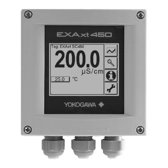
4.1 Main Display and Trending Graphics
Overview of main display functions and using trending graphics.
4.3 Zoom In On Details
Viewing actual mA values, contact status, and calibration information.
4.5 Setup-Calibration & Commissioning
Navigating menus for setup, calibration, and commissioning.
4.7 Menu Structure Navigation
Overview of how to navigate through the converter's menu system.
5. Menu Structure Commissioning
5.1 Configure Sensor
Selecting sensor type, units, and entering cell constant.
5.2 Temperature Setting & Compensation
Configuring temperature sensor, units, and compensation methods.
5.4 Calibration Settings
Defining limits and intervals for calibration procedures.
5.5 Concentration Measurement
Setting up concentration measurement using tables.
5.6 mA Output Setup
Configuring control modes (P, PI, PID) and output behavior for mA signals.
5.7 Contact Output Setup
Assigning functions like Alarm, Hold, Fail to contact outputs.
5.8 Fail Conditions
Defining how the converter reacts to fail situations.
5.9 Simulate Function
Simulating contact outputs or percentage of output for testing.
5.10 USP Monitoring
Setting up for Water for Injection monitoring.
5.11 Input Contacts & 5.12 Error Configuration
Configuring input contacts and managing error notifications.
5.13 Logbook & 5.14 Advanced Setup
Managing logbooks and configuring advanced settings like defaults and passwords.
5.15 Display Setup
Customizing main display, adding text, and setting trend graph parameters.
6. Calibration
Cell Constant Calibration (Manual & Automatic)
Procedures for calibrating the cell constant using manual or automatic methods.
Air, Sample, and Temperature Calibration
Performing zero, sample, and temperature calibration routines.
Calibration Best Practices
General comments and considerations for effective conductivity calibration.
7. Maintenance
7.1 Periodic Maintenance
Information on maintaining the converter unit, including battery and fuse.
7.2 Periodic Sensor Maintenance
Guidelines for maintaining the conductivity sensor's performance and accuracy.
7.3 Cleaning Methods
Recommended cleaning procedures for sensors and the unit.
7.4 LCD Adjustment
Adjusting display contrast and calibrating the touchscreen.
8. Troubleshooting
Understanding Status and Error Indicators
Interpreting information, warning, and fail flags on the main display.
Diagnostic Checks (Calibration & Polarization)
Performing calibration checks and monitoring polarization for sensor health.
Predictive Maintenance and Error Actions
Using predictive maintenance features and responding to error displays.
8.6 Error Displays and Actions
Detailed interpretation of error messages and required actions.
Appendices
Appendix 1: Temperature Compensation
Detailed explanation of temperature effects on conductivity and compensation calculations.
Appendix 2: TDS Readings
Concept of Total Dissolved Solids and its relation to conductivity.
Appendix 3: Calibration Solutions
Guidance on selecting and using calibration solutions for conductivity.
Appendix 4: Sensor Selection
Guide to selecting appropriate sensors based on application and measurement range.
Appendix 5: Entering Cell Constant
Procedure for manually entering the cell constant for specific sensor models.
Appendix 6: HART HHT Menu Structure
Overview of the HART handheld terminal menu for configuration.
Appendix 7: FM Approval Control Drawing
Wiring diagram for FM approval compliance.
Customer Maintenance Parts List
Spare Parts Identification
List of available spare parts for the SC450G converter with part numbers.
Revision Record
Manual Update History
History of changes and updates made to the manual over different editions.
Need help?
Do you have a question about the Exaxt450 and is the answer not in the manual?
Questions and answers