
Related Manuals for YOKOGAWA av550g


Summary of Contents for YOKOGAWA av550g
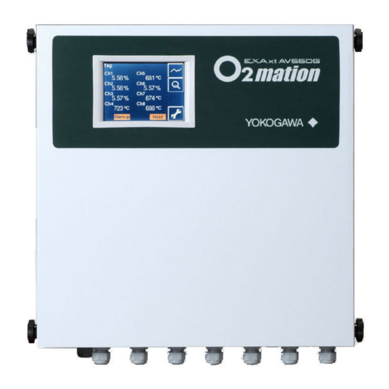
- Page 1 User’s Manual Model AV550G Zirconia Oxygen Analyzer Averaging Converter IM 11M12D01-01E IM 11M12D01-01E 7th Edition...
- Page 2 For the AV550G system, various types of EXAxt ZR Series detectors as well as optional accessories are available. The best measurement can be achieved by selecting instruments appropriate to your application.
- Page 3 Major parts and function are described in this manual 7. Startup Basic procedure to start operation of AV550G. Chapter 7 enables you to operate the equipment immediately. 8. Detailed Data Details of key operations and displays ...
- Page 4 For the safe use of this equipment WARNING The AV550G is very heavy. Handle it with care. Be sure not to accidentally drop it. Handle safely to avoid injury. When carrying the AV550G Averaging Converter, make sure this is done by two or more people.
- Page 5 Refer to Chapter 2 Specifications for the list of model codes. Details on operation parameters When the AV550G Averaging Converter arrives at the user site, it will operate based on the operation parameters (initial data) set before shipping from the factory.
- Page 6 Batteries are included in this product. Batteries incorporated into this product cannot be removed by yourself. Dispose them together with this product. When you dispose this product in the EU, contact your local Yokogawa Europe B.V.office. Do not dispose them as domestic household waste.
- Page 7 Failure of components which are out of scope of warranty stated in instruction manual. l Failure caused by usage of software, hardware or auxiliary equipment, which Yokogawa did not supply. l Failure due to improper or insufficient maintenance by user.
-
Page 8: Table Of Contents
Separate type Detector for High Temperature and Related Equipment ..2-8 2.3.1 ZR22G (0.15m) Separate type Detector for High Temperature ..2-8 2.3.2 ZO21P High Temperature Probe Adapter ......... 2-9 AV550G Averaging Converter ................ 2-11 2.4.1 Standard Specifications ..............2-11 2.4.2 Functions..................2-12 ZA8F Flow Setting Unit ................... - Page 9 Toc-2 <CONTENTS> 3.1.1 Installation Location ................3-1 3.1.2 Probe Insertion Hole ................3-1 3.1.3 Installation of the Detector ..............3-2 3.1.4 Installation of the Dust Filter (K9471UA), Dust Guard Protector (K9471UC), Probe Protector ZO21R ..........3-3 Installation of High Temperature Detector (ZR22G-015) .......................
- Page 10 ZR22G Detector ....................6-1 6.1.1 General-purpose Detector (except for Model ZR22G-015) ....6-1 6.1.2 High Temperature Detector (Model ZR22G-015) ......6-2 AV550G Averaging Converter ................6-3 6.2.1 Components and Function ..............6-3 6.2.2 Touchpanel Switch Operations ............6-3 ZA8F Flow Setting Unit ................... 6-12 Startup .......................
- Page 11 Toc-4 <CONTENTS> 7.11.2 Checking contacts used to operate solenoid valves during automatic calibration ..................7-12 7.11.3 Checking Contact Inputs ..............7-12 Setting Operating Parameters - Detail, and Examples ......8-1 Setting Analog Outputs ..................8-1 8.1.1 Analog Output Range (Per-Channel) ..........8-1 8.1.2 Setting Output Hold (Applies to All Outputs) ........
- Page 12 Toc-5 <CONTENTS> 10.1.6 Span gas and Zero gas Correction Ratios ........10-2 10.1.7 Cell Response Time ................. 10-3 10.1.8 Robustness of a Cell ................ 10-3 10.1.9 Cell’s Internal Resistance ..............10-3 10.1.10 Recommended Next Calibration Date ..........10-4 10.1.11 Heater ON-Time Ratio ............... 10-4 10.1.12 Time ....................
- Page 13 Toc-6 <CONTENTS> Inspection and Maintenance ..............11-1 11.1 Removing and Attaching the Front Cover ........... 11-2 11.1.1 Removing the Front Cover ............... 11-2 11.1.2 Attaching the Front Cover ..............11-2 11.2 Hot Swap Function ..................11-2 11.3 Inspection and Maintenance of the Detector ..........11-4 11.3.1 Cleaning the Filter in Sensor Assembly ...........
-
Page 14: Overview
A multiple point oxygen measurement system may be required for situations when gas stratification in the flue duct affects combustion control. The AV550G Averaging Converter can accept inputs from up to eight zirconia oxygen detectors. It sends output signals for the individual as well as averages of multiple oxygen concentrations. -
Page 15: System Configuration To Perform Automatic Calibration
Output signal cable (Cell output, thermocouple output, cold contact compensation) (0.75mm , 6-core shield cable) Heater power , 2-core shield cable) (1.25mm Model AV550G Averaging Converter Analog outputs : Averaged and individual outputs 4 to 20 mA DC Digital output Stop... -
Page 16: System Components
1.2.1 System Components and Their Applicability Model, Part Number or System 1 System 2 Item Specifications Manual Calibration Automatic Calibration Averaging Converter AV550G- (A or B) Detector See Chapter 1.2.2 Flow setting unit ZA8F Needle valve For flow control ... - Page 17 Blank Page...
-
Page 18: Specifications
Measured Object: Oxygen concentration in combustion exhaust gas and mixed gas (excluding inflammable gases, may not be applicable corrosive gas such as ammonia is present — check with Yokogawa) Measurement System: Zirconia system Oxygen concentration: 0.01 to 100 vol% O Output Signal: 4 to 20 mA DC (maximum load resistance 550 Ω) -
Page 19: General-Purpose Separate Type Detector And Related Equipment
150 kPa. When with a check valve and a ZR40H Automatic Calibration Unit, it is 200 kPa. If the pressure of your sample gas exceeds these limits, consult with Yokogawa. Probe Length: 0.15, 0.4, 0.7, 1.0, 1.5, 2.0, 2.5, 3.0, 3.6, 4.2, 4.8, 5.4 m... - Page 20 < 2. Specifications > Terminal Box Case: Material; Aluminum alloy Terminal Box Paint Color: Case; Mint green (Munsell 5.6BG3.3/2.9) Cover; Mint green (Munsell 5.6BG3.3/2.9) Finish: Polyurethane corrosion-resistant coating Gas Connection: Rc1/4 or 1/4 FNPT Wiring Connection: G1/2, Pg13.5, M20 by 1.5 mm, 1/2 NPT Installation: Flange mounting Probe Mounting Angle: Horizontal to vertically downward.
- Page 21 < 2. Specifications > Model and Codes Style : S2 Model Suffix code Option code Description ZR22G - - - - - - - - - - - - - - - - - - - - - - - - - - - - - - - - - - - - - - - - - - - - Separate type Zirconia Oxygen Analyzer, Detector Length...
- Page 22 < 2. Specifications > EXTERNAL DIMENSIONS 1. Model ZR22G Separate type Zirconia Oxygen Analyzer, Detectors 283 to 292 Unit : mm L=0.15, 0.4, 0.7, 1.0, 1.5, 2.0, 2.5, 3.0, 3.6, 4.2, 4.8, 5.4 (m) Rc1/4 or 1/4 NPT Reference gas inlet 155 to 163 2-G1/2,2-1/2 NPT etc.
- Page 23 < 2. Specifications > 2. Model ZR22G...-P (with pressure compensation) Separate type Zirconia Oxygen Analyzer, Detectors L=0.15, 0.4, 0.7, 1.0, 1.5, 2.0, 2.5, 3.0, 3.6, 4.2, 4.8, 5.4 (m) Rc1/4 or 1/4 NPT Reference gas inlet 2-G1/2, 2-1/2 NPT etc. Cable connection port Reference gas outlet PIPING...
-
Page 24: Zo21R Probe Protector
< 2. Specifications > 2.2.2 ZO21R Probe Protector Used when sample gas flow velocity is approx. 10 m/sec or more and dust particles wears the detector in cases such as pulverized coal boiler of fluidized bed furnace (or burner) to protect the detector from wearing by dust particles. -
Page 25: Separate Type Detector For High Temperature And Related Equipment
< 2. Specifications > Separate type Detector for High Temperature and Related Equipment 2.3.1 ZR22G (0.15m) Separate type Detector for High Temperature Standard Specifications Construction: Water-resistant, non-explosion-proof Probe length: 0.15 m Terminal box: Aluminum alloy Probe material in contact with gas: SUS 316 (JIS) (Probe), SUS 304 (JIS) (Flange), Zirconia (Sensor), Hastelloy B, (Inconel 600, 601) Weight: Approx. -
Page 26: Zo21P High Temperature Probe Adapter
< 2. Specifications > 2.3.2 ZO21P High Temperature Probe Adapter Measuring O in the high temperature gases (exceeds 700°C) requires a general-purpose detector ZR22G of 0.15 m length and a high temperature probe adapter. Sample gas temperature: 0 to 1400°C (when using SiC probe) 0 to 800°C (when using SUS 310S probe) Sample gas pressure: -0.5 to + 5 kPa. - Page 27 2-10 < 2. Specifications > Unit: mm Approx. 351 Sample gas outlet Flange (Thickness 5) JIS 5K 32 FF equivalent Rc1/2(Note2) Gasket (Thickness 1.5) Ø60.5 ØA Flange <1> Detector(ZR22G) Flange provided by customer Approx. 48 Ø52 over Reference gas inlet Rc1/4 or 1/4 NPT High temperature Probe SiC pipe Ø30...
-
Page 28: Av550G Averaging Converter
2-11 < 2. Specifications > AV550G Averaging Converter 2.4.1 Standard Specifications Compatibility of Detectors : ZR22G, ZO21D, ZO21DW Number of Detectors : 1 to 8 (100 V type), Expandable up to 8 1 to 4 (200 V type), Expandable up to 4 (Note) Specify 4 Channel Base when 200V type is selected. -
Page 29: Functions
2-12 < 2. Specifications > Safety and EMC conforming standards Safety: Conforms to EN 61010-1, CAN/CSA-C22.2 No. 61010.1 certified, UL Std. No. 61010-1 certified EMC: Conforms to EN 61326-1 Class A, Table 2 *, EN 61326-2-3, EN 61000-3-2, EN 61000-3-3 * : Influence of immunity environment (Criteria A ) : ±12.5% of F. - Page 30 2-13 < 2. Specifications > Validation Function: Permits control room activation of zero, span or midpoint gas concentrations without running an actual calibration. Blow back Function: Output through the contact in the set period and time. Auto/Semi-auto selectable. Maintenance Functions: Can operate updated data settings in daily operation and checking. Display data settings, calibration data settings, blow back data settings, current output loop check, input/output contact check.
- Page 31 2-14 < 2. Specifications > Output damping; 0 to 255 seconds. Hold/non-hold selection, preset value setting possible with hold. Contact Output: 5 points, contact capacity 30 V DC 3 A, 250 V AC 3 A (resistive load) Four of the output points can be selected to either normally energized or normally deenergized status.
-
Page 32: Standard Accessories
(*3) When suffix code “-2” (230 V AC) is selected, select code “-A” (4 Channel Base). (*4) When suffix code “-F” (FOUNDATION Fieldbus communication) is selected, used exclusively for communication. When using AV550G as CE marking compliance product, select HART communication. (*5) Input 01 to 30 in . - Page 33 2-16 < 2. Specifications > Channel Card Model Suffix Code Option Code Description AV55CM - - - - - - - - - - - - - - - - - - - - - - - - - - Channel Card Number of 1 Oxygen Channel Card, Common Isolation...
- Page 34 2-17 < 2. Specifications > • External Dimensions Unit: mm (without knob) 166.5 4-knobs Extension view Distance between mounting hole 10-M5 holes Maintenance space F2-5E.ai IM 11M12D01-01E...
-
Page 35: Za8F Flow Setting Unit
Calibration gas (zero gas, span gas) Consumption: Approx. 0.7 l/min (at calibration time only) Weight: Approx. 2.3 kg NOTE Use instrument air for span calibration gas, if no instrument air is available, contact Yokogawa. Model and Codes Model Suffix code... - Page 36 2-19 < 2. Specifications > ● External Dimensions Unit : mm ø6 Hole REFERENCE CHECK JIS 50A (60.5mm) REFERENCE SPAN ZERO mounting pipe 235.8 222.8 Calibration gas outlet Span gas inlet Reference gas outlet Zero gas inlet Piping connection port A CHECK SPAN ZERO...
-
Page 37: Other Equipments
2-20 < 2. Specifications > Other Equipments 2.6.1 Dust Filter for the Detector (K9471UA) This filter is used to protect the detector sensor from a corrosive dust components or high velocity dust in recovery boilers and cement kilns. Sample gas flow rate is needed to be 1 m/sec or more to replace gas inside zirconia sensor. •... -
Page 38: Ejector Assembly For High Temperature (E7046Ec, E7046En)
2-21 < 2. Specifications > 2.6.3 Ejector Assembly for High Temperature (E7046EC, E7046EN) This ejector assembly is used where pressure of sample gas for high temperature detector is negative. This ejector assembly consists of an ejector, a pressure gauge assembly and a needle valve. - Page 39 2-22 < 2. Specifications > Needle valve Pressure gauge Ejector Air source Graph 1 Graph 2 Po (kPa) Qa (l/min) P= 0.5 P (kPa) L (m) Pressure setting characteristics Air consumption characteristics Sample Gas Graph 3 Graph 4 Pg (kPa) (kPa) : Pressure setting Qg (l/min)
-
Page 40: Stop Valve (L9852Cb, G7016Xh)
2-23 < 2. Specifications > 2.6.4 Stop Valve (L9852CB, G7016XH) This valve mounted on the calibration gas line in the system using ZA8F flow setting unit for manual calibration. Standard Specifications Material: SUS 316 (JIS) Connection: Rc 1/4 or 1/4 FNPT Weight: Approx. -
Page 41: Air Set
2-24 < 2. Specifications > 2.6.6 Air Set This set is used to lower the pressure when instrument air is used as the reference and span gases. Standard Specifications • G7003XF, K9473XK Primary Pressure: Max. 1 MPa G Secondary Pressure: 0.02 to 0.2 MPa G Connection: Rc1/4 or 1/4 FNPT (with joint adapter) - Page 42 2-25 < 2. Specifications > 2.6.7 Zero Gas Cylinder (G7001ZC) The gas from this cylinder is used as the calibration zero gas and detector purge gas. Standard Specifications Capacity: 3.4 l Filled Pressure: 9.8 to 12 MPa G Composition: 0.95 to 1.0 vol% O in N Weight: Approx.
-
Page 43: Zero Gas Cylinder (G7001Zc)
2-26 < 2. Specifications > 2.6.9 Case Assembly for Calibration Gas Cylinder (E7044KF) This case assembly is used to store the zero gas cylinders. Standard Specifications Installation: JIS 50A (Ø 60.5 mm) pipe mounting Material: SPCC (Cold rolled steel sheet) Case Paint: Baked epoxy resin, Jade green (Munsell 7.5 BG 4/1.5) Weight:... - Page 44 2-27 < 2. Specifications > • External Dimensions Jig for change Unit : mm (K9470BX) L ± 12 Model & Codes Weight (kg) ZR22A-015 Approx. 0.5 ZR22A-040 Approx. 0.8 ZR22A-070 Approx. 1.2 ZR22A-100 1152 Approx. 1.6 ZR22A-150 1652 Approx. 2.2 ZR22A-200 2152 Approx.
- Page 45 Blank Page...
-
Page 46: Installation
This chapter describes installation of the following equipment: Section 3.1 General-purpose Detector (except ZR22G-015) Section 3.2 High Temperature Detector (ZR22G-015) Section 3.3 AV550G Averaging Converter Section 3.4 ZA8F Flow Setting Unit Section 3.5 Case Assembly (E7044KF) Installation of General-purpose Detector 3.1.1... -
Page 47: Installation Of The Detector
< 3. Installation > (1) Do not mount the probe with the tip higher than the probe base. (2) If the probe length is 2.5 meters or more, the detector should be mounted vertically (no more than a 5° tilt). (3) The detector probe should be mounted at right angles to the sample gas flow or the probe tip should point downstream. -
Page 48: Installation Of The Dust Filter (K9471Ua), Dust Guard Protector (K9471Uc), Probe Protector Zo21R
< 3. Installation > 3.1.4 Installation of the Dust Filter (K9471UA), Dust Guard Protector (K9471UC), Probe Protector ZO21R <Procedures for installation of the dust filter (K9471UA)> CAUTION • The dust filter is used to protect the Zirconia sensor from corrosive dust or a high concentration of dust such as in utility boilers and cement kilns. - Page 49 (3) Where the detector is mounted horizontally, the reference gas and calibration gas inlet should face downward. When the probe length of the ZR22G is more than 2m, consult Yokogawa. NOTE When the probe protector is used in the ZR22G with pressure compensation (-P), instrument air leaking from the probe protector may affect the measured value.
-
Page 50: Installation Of High Temperature Detector (Zr22G-015)
< 3. Installation > Unit: mm Gasket (Thickness 3.0) 1050,1550,2050 Flow direction of the sample gas Probe top Mount the protector so that the notch is the downstream side of the gas flow. Reference gas inlet Calibration gas inlet F3-5E.ai Figure 3.4 Probe protector (for dust wear protect) Installation of High Temperature Detector (ZR22G-015) -
Page 51: Probe Insertion Hole
< 3. Installation > (3) When the probe adapter is surrounded by a heat insulator, remove the heat insulator. Ensure that the temperature of the probe adapter does not fall below the dew point of the gas in winter. (4) To prevent temperature rises due to radiant heat, insert heat insulator between the wall of the furnace and the probe adapter. - Page 52 < 3. Installation > • The same applies to the high temperature probe adapter with a probe made of silicon carbide (SiC). • A gasket should be used on the flange surface to prevent gas leakage. The gasket material should be selected depending on the characteristics of the sample gas. It should be heatproof and corrosion-proof.
-
Page 53: Installation Of The Averaging Converter
< 3. Installation > Installation of the Averaging Converter The averaging converter is designed for indoor installation and should be installed in the instrument panel in a control room. For outdoor installation, the averaging converter should be installed in an outdoor instrument panel protected from direct sunlight and the weather. -
Page 54: Installation In An Instrument Panel
< 3. Installation > (9) The converter should be near the detectors: the two-way resistance between detector and converter should not exceed 10Ω. WARNING The averaging converter is heavy. Take extra care not to accidentally drop it. Installation work should be done by an adequate number of people. -
Page 55: Outdoor Installation
(2) Preventing Excessive Temperature Rise in an Instrument Panel Use a cooling method such as one of those shown in Figure 3.9 if there is a danger of the temperature inside an instrument panel exceeding the temperature range limits. ∞ ∞ AV550G AV550G AV550G ○ ○... -
Page 56: Installation Of Za8F Flow Setting Unit
3-11 < 3. Installation > Installation of ZA8F Flow Setting Unit 3.4.1 Installation Location The following should be taken into consideration: (1) Easy access to the unit for checking and maintenance work. (2) Near to the detector or the converter. (3) No corrosive gas. -
Page 57: Installation Of The Case Assembly(E7044Kf)
3-12 < 3. Installation > Installation of the Case Assembly(E7044KF) The case assembly is used to store the G7001ZC zero gas cylinders. 3.5.1 Installation Location The following should be taken into consideration: (1) Easy access for cylinder replacement. (2) Easy access for checking. (3) Near to the detector or converter as well as the flow setting unit. -
Page 58: Piping
< 4. Piping > Piping This chapter describes piping procedures for the AV550G Zirconia Oxygen Analyzer Averaging Converter system based on two typical system configurations. Piping for a System Using Flow Setting Units for Manual Calibration The piping for a system using flow setting units for manual calibration is shown in Figure 4.1. -
Page 59: Parts Required For Piping In A System Using Flow Setting Units For Manual Calibration
Yokogawa recommended: G7003XF/K9473XK or inlet G7004XF/K9473XG Connection fitting R1/4 or 1/4 NPT (male) General parts Sample gas * Auxiliary ejector Yokogawa recommended: E7046EC or E7046EN outlet assembly * Equal tee, General parts Rc1/4 or 1/4 NPT (female) connection fitting * Needle valve... -
Page 60: Piping For The Calibration Gas Inlet
40°C. Mount a regulator valve (specified by Yokogawa) on the cylinder. Mount a check valve or stop valve (specified by Yokogawa) on the nipple (found on the local market) at the calibration gas inlet of the detector as illustrated in Figure 4.2. - Page 61 < 4. Piping > • If the temperature of a sample gas is high and its pressure exceeds 0.49 kPa, the temperature of the sample gas at the detector may not be below 700°C. In this case, connect a needle valve (found on the local market) through a nipple (found on the local market) to the sample gas outlet (Rc1/2) of the probe adapter so that the sample gas exhaust volume can be restricted.
-
Page 62: Piping For Blow Back
• Blow pipe (to be prepared as illustrated in Figure 4.7.) • Two-way solenoid valve: “ Open “ when electric current is on. (Found on the local market) • Air set (Yokogawa recommended: G7003XF / K9473XK or G7004XF / K9473XG) <Blow pipe manufacturing>... -
Page 63: Piping For Indication Check
< 4. Piping > 4.1.6 Piping for Indication check To perform an indication check using the third check gas, the piping to allow the third gas to flow into the calibration gas line is required for the ZA8F Flow Setting Unit in addition to the system configuration shown in Figure 4.1. -
Page 64: Piping To Introduce Purge Gas When A Process Gas Alarm Occurs
It is recommended that each instrument be installed to allow for minimum piping between the ZA8F Flow Setting Unit and the detector and between the solenoid valve for introducing the purge gas and the detector. Averaging Converter (AV550G) Detector Analog outputs:... -
Page 65: Piping For A System To Perform Automatic Calibration
< 4. Piping > Piping for a System to Perform Automatic Calibration The piping for a system to perform automatic calibration is shown in Figure 4.10. Averaging Converter (AV550G) Detector Signal Analog outputs: Averaged and Heater individual outputs Solenoid valve... - Page 66 If optional 24 V outputs are specified for solenoid valves (Option Code “/24”), no external power supply for solenoid valve is required. The solenoid valves are powered from the AV550G Averaging Converter. Never connect external power sources in the wiring for solenoid valves.
-
Page 67: Parts Required For Piping In A System To Perform Automatic Calibration
Yokogawa recommended: G7003XF/K9473XK or G7004XF/K9473XG Connection fitting R1/4 or 1/4 NPT (male) General parts Sample gas * Ejector assembly Yokogawa recommended: E7046EC or E7046EN outlet * Equal tee, General parts Rc1/4 or 1/4 NPT (female) connection fitting * Needle valve... -
Page 68: Piping For The Calibration Gases
(Yokogawa recommended part) and where necessary, a stop valve. • Install a normally closed solenoid valve (Yokogawa recommended part) through a nipple (found on the local market) on the calibration gas inlet of the detector as shown in Figure 4.11. This solenoid valve is activated by a contact signal from the averaging converter. -
Page 69: Piping To The High Temperature Probe Adapter
*: If optional 24 V outputs are specified for solenoid valve (MS Code "/24"), no external power supply for solenoid valves is required. The solenoid valves are powered from the AV550G Averaging Converter. Never connect external power sources in the wiring for solenoid valves. -
Page 70: Piping To Introduce Purge Gas When A Process Gas Alarm Occurs
* : If optional 24 V outputs are specified for solenoid valve (MS Code "/24"), no external power supply for solenoid valves is required. The solenoid valves are powered from the AV550G Averaging Converter. Never connect external power sources in the wiring for solenoid valves. - Page 71 Blank Page...
-
Page 72: Wiring
The specified number of channel cards per purchase order is factory installed in channels in order from CH1. The factory-installed channels can be changed as desired. All the channels are the same. Note that in a 4-channel base averaging converter (AV550G-A-), channels CH5 to CH8 cannot be used. - Page 73 < 5. Wiring > WARNING Cables that withstand temperatures of at least 80°C should be used for wiring. CAUTION Using a channel card installed without 2 screws tightened, may result in poor resistance to noise. Precautions in Processing Shields When a shielded cable is required for wiring, follow the instructions below to process the shield. (1) All the shields should be connected on the averaging converter side: Connect to the cable shield ground terminals inside the averaging converter.
-
Page 74: Wiring Holes
< 5. Wiring > 5.1.2 Wiring Holes The averaging converter has 30 wiring holes. Use holes near the rear for power wiring (e.g., power cables, detector heater wires, and wiring for solenoid valve contacts and other contact outputs). For signal wiring (e.g., detector signal lines and analog output signal lines), use holes near the front. If more than 30 cables are used and thus more than one cable has to be passed through one wiring hole, do not allow signal lines and power lines to pass the same hole. -
Page 75: Types Of Wiring And Cables
< 5. Wiring > 5.1.4 Types of Wiring and Cables Types of wiring and cables to be used are listed in Table 5.1. The purpose of a shield is not only to prevent the effect from noise disturbance but also to restrict the noise emitted from the converter. Specified cables must be used. -
Page 76: Wiring For The Averaging Converter And Peripheral Devices
< 5. Wiring > Wiring for the Averaging Converter and Peripheral Devices 5.2.1 Preparation for Wiring to the Averaging Converter Follow the instructions below when connecting cables to the averaging converter. (1) The terminal screws on the control and channel cards are M3.5, and all the other terminal screws are M4. -
Page 77: Power And Ground Wiring
< 5. Wiring > Notice when closing the cover of the detector. CAUTION • Before opening the detector cover, loosen the lock screw. If the screw is not loosened first, the screw will damage the cover, and the terminal box will require replacement. When opening and closing the cover, remove any sand particles or dust to avoid gouging the thread. -
Page 78: Power Wiring To Detector Heaters
< 5. Wiring > 5.2.4 Power Wiring to Detector Heaters This wiring provides electric power from the averaging converter to the heater for heating the sensor in a detector. Use 2-core shielded cables that withstand temperatures of at least 80°C. The wire size should be 1.25 mm (16 AWG) or larger and the conductor two-way resistance should be 10 Ω... -
Page 79: Signal Wiring To Detectors
< 5. Wiring > 5.2.5 Signal Wiring to Detectors This wiring is for transmitting signals of cell electromotive force, thermocouple output and cold junction compensation from a detector to the averaging converter. Use 6-core shielded cables that withstand temperatures of at least 80°C. The conductor two-way resistance should be 10 Ω or less. Keep the cables away from the power wiring. -
Page 80: Ground Wiring Of Detectors
< 5. Wiring > 5.2.6 Ground Wiring of Detectors Connect the ground wiring to the external ground terminal on the detector case or the internal ground terminal. Follow the instructions below. The ground terminal screw is M4. (1) The ground resistance should be 100 Ω or less (equivalent to Class D grounding). (2) If the ambient temperature of the wiring installation exceeds 75°C, use appropriate heat resistant wires. -
Page 81: Wiring For Solenoid Valve For Automatic Calibration
If optional 24 V outputs are specified for solenoid valves (Option Code “/24”), no external power supply for solenoid valves is required. The solenoid valves are powered from the AV550G Averaging Converter. The maximum current that can be supplied to the solenoid valve is 50 mA. Use solenoid valves that consume not more than 1.2 W to operate. -
Page 82: Wiring For Individual/Common Error Contact Outputs And Functional Contact Outputs
5-11 < 5. Wiring > 5.2.9 Wiring for Individual/Common Error Contact Outputs and Functional Contact Outputs The averaging converter has the following contact outputs. (1) Functional contact outputs (DO1 to DO4): User specified functions can be assigned. (2) Common error contact output (DO5): Activated when any error occurs. (3) Individual error contact outputs (DO-CH1 to DO-CH8): Channel-specific contacts. -
Page 83: Wiring For Contact Inputs
5-12 < 5. Wiring > 5.2.10 Wiring for Contact Inputs The averaging converter receives contact inputs to perform the specified functions. Follow the instructions below to run the wiring for contact inputs. Use 2-core or 3-core cable that withstand temperatures of at least 80°C for this wiring. The number of cores is determined by the number of contacts to be used. -
Page 84: Wiring And Piping Examples
: If optional 24 V outputs are specified for solenoid valves (Option Code "/24"), no external power supply for solenoid valves is required. The solenoid valves are powered from the AV550G Averaging Converter. Never connect external power sources in the wiring for solenoid valves. -
Page 85: Wiring And Piping For Blow Back
: If optional 24 V outputs are specified for solenoid valves (Option Code "/24"), no external power supply for solenoid valves is required. The solenoid valves are powered from the AV550G Averaging Converter. Never connect external power sources in the wiring for solenoid valves. -
Page 86: Components
< 6. Components > Components In this Chapter, the names and functions of components are described for the major equipment of the AV550G Averaging Converter. ZR22G Detector 6.1.1 General-purpose Detector (except for Model ZR22G-015) Terminal box, Non-explosion-proof JIS C0920 / equivalent to IP44D. -
Page 87: High Temperature Detector (Model Zr22G-015)
< 6. Components > 6.1.2 High Temperature Detector (Model ZR22G-015) Sample gas outlet When a negative measurement gas pressure is used, connect the auxiliary ejector assembly. When the measurement gas is high temperature and high-pressure, and does not fall below 700°C, Separate type High temperature Detector (ZR22G-015) connect a pressure control valve When the temperature of the measurement gas is... -
Page 88: Av550G Averaging Converter
• G (connected to internal protective ground terminal by jumper plate) • Internal protective ground terminal F6-3E.ai Figure 6.3 Components and Function of AV550G 6.2.2 Touchpanel Switch Operations Panels and Switches The averaging converter uses touchpanel switches which can be operated by just touching the panel display. - Page 89 < 6. Components > On this display, touch the indication area (enclosed by dotted line) of the desired channel. A display shown in bottom in Figure 6.4 will appear. This display will show the oxygen concentration (or cell temperature during warm-up) and average concentration data (groups a, b, and c) (show “---” if all channels are in warm-up period) of the selected channel, which is called a single-channel display.
- Page 90 < 6. Components > Table 6.1 Types of Status Indication Markings Marking Condition Displayed if any of the calibration gas channels is being purged. Purge Displayed if any channel is in warmup status. If any other channel Warmup is in Purge status then Purge status display takes preference. Channel is in calibration period: calibration gases are being CAL.TIME introduced.
-
Page 91: Display Configuration
Alarm setup Contact setup Indication check Blow back Average group setup Manual ind. check Start blow back Others Semi-auto ind. check Cancel blow back Enter Enter Enter F6-5E.ai Figure 6.5 Display Configuration of AV550G IM 11M12D01-01E... - Page 92 < 6. Components > Display Functions 1) Basic panel display (Displays measured oxygen concentrations, and cell temperatures during warm-up period.) The basic panel display consists of a multi-channel display and a single-channel display. The multi-channel display screen shows cell temperatures during warm-up period and oxygen concentrations afterward.
- Page 93 < 6. Components > 2) Detailed data display To move to the detailed data display, touch the Detailed data key and then touch the indication area of the desired channel in the multi-channel display, or simply touch the Detailed data key in the single- channel display.
- Page 94 < 6. Components > 4) Execution/Setup display Touch the Setup key on the basic panel display. The Execution/Setup display will appear. From the menu items — calibration, indication check, blow back, maintenance, or commissioning, select the desired item to perform. Execution/Setup Execution Calibration...
- Page 95 6-10 < 6. Components > 8) Maintenance display From the menu on the Execution/Setup display, select Maintenance. The Maintenance display will appear. The following can be performed from the menu on this display. 1. Display setup 2. Calibration, Indication check, and Blow back setups 3.
- Page 96 6-11 < 6. Components > To enter a password (in combination with text data, numeric values and codes), the alphabetic character entry panel display first appears. If you press any numeral key (0 to 9), the current display then changes to the numeric-value entry panel display, enabling you to enter numeric values. If you press the “other”...
-
Page 97: Za8F Flow Setting Unit
6-12 < 6. Components > ZA8F Flow Setting Unit Reference gas flow setting valve Span gas flow setting valve Zero gas flow setting valve Flowmeter for reference gas Flowmeter for calibration gas F6-18E.ai Figure 6.18 ZA8F Flow Setting Unit IM 11M12D01-01E... -
Page 98: Startup
< 7. Startup > Startup This Chapter explains the startup procedures for the Averaging Converter: supplying power, setting parameters as required, and performing manual calibration. Startup Procedure The startup procedure is as follows: CAUTION If you connect Model ZO21D detectors, then you need to change the detector parameters. Before connecting power, refer to: Section 7.4 Setting Detector Model. -
Page 99: Set Valve Type
< 7. Startup > Set Valve Type Set valves (which depend on your system configuration) as follows: 1) If there is a shut-off valve at the calibration gas inlet, shut it. 2) Assuming that instrumentation air supply is used as the reference gas, adjust air set secondary pressure to approximately 50 kPa above that of the sample gas -- if there is a check valve, then adjust it to approximately 150 kPa above that of the sample gas (but pressure should be no greater than 300 kPa). - Page 100 < 7. Startup > [Disconnect power to the heater; this will generate an error ] If you disconnect the signal wiring from the detector then this will generate an error, but this allows you to change the detector model settings without detector warm up. 1) Remove all thermocouple (TC) signal wiring from channel cards which connect to ZO21D detectors.
-
Page 101: Supply Power To Averaging Converter
< 7. Startup > Supply Power to Averaging Converter CAUTION To avoid temperature changes around the sensor, it is recommended that (rather than turning it on and off) power be continuously supplied to the Averaging Converter if it is used in an application where it is used periodically. -
Page 102: Selection Of Gas To Be Measured
< 7. Startup > Selection of Gas to be Measured Exhaust gas includes steam resulting from combustion of hydrogen and oxygen. You may choose whether to display the oxygen concentration including the oxygen contained in the steam, or display the computed “dry” oxygen concentration (a value compensated for the oxygen in steam) which results in a higher concentration value. -
Page 103: Averaging Group Setting
< 7. Startup > Averaging Group Setting The AV550G can determine oxygen concentration average for three averaging groups a, b, and c. a and b can each be arbitrary channel groupings, and the corresponding averages are output. c output is (a+b) /2. Select the groupings for a and b as per the procedure below. -
Page 104: Calibration
< 7. Startup > Calibration To calibrate this instrument, the procedure is to measure zero gas and span gas and set the instrument to read the known concentrations. The procedure for both zero and span calibration, or for either zero or span calibration, can be performed manually from the touch display, or can be performed semi-automatically using contact signal inputs to start calibration, (allowing preset calibration and stabilization times), or it can be performed automatically at preset intervals. -
Page 105: Performing Manual Calibration
< 7. Startup > 7.9.2 Performing Manual Calibration 1) Confirm that the zero gas flow setting valve is fully closed, then adjust supply gas pressure to measurement gas pressure + 50kPa (but a maximum of 300 kPa) using the valve on the gas cylinder. - Page 106 < 7. Startup > 8) Open the span gas flow setting valve, and adjust flow to 600 ± 60 ml/min. 9) Select [Valve opened (Start Calibration)] and touch the Enter key. An oxygen concentration graph like Figure 7.13 is displayed, and [CAL.TIME] status mark flashes. Wait for the graph measured value trace to stabilize.
-
Page 107: Analog Output Current Loop Check
7-10 < 7. Startup > 15) When the graph trace stabilizes, touch the Enter key. The display changes to like Figure 7.16. The measured value is adjusted to read the same as the zero gas concentration set value, and a check mark appears in the check box beside Zero calibration. -
Page 108: Checking Operation Of Contact Input, Contact Output
7-11 < 7. Startup > 5) Select the Analog output to perform Loop check on, and touch the Enter key. 6) The numerical entry display appears. Set output current somewhere in the range 4 to 20 mA. Touching the Entry key outputs this current value. 7) Touching the Reject key (door with arrow) from the numerical entry display returns you to the “mA-output loop check”... -
Page 109: Checking Contacts Used To Operate Solenoid Valves During Automatic Calibration
7-12 < 7. Startup > 7.11.2 Checking contacts used to operate solenoid valves during automatic calibration 1) From the Contact check display of Figure 7.18 select [Solenoid valve contacts]. From the corresponding Solenoid valve contacts select display of Figure 7.20 select the solenoid to check. To check the automatic calibration gas switching valve, select [Com]. -
Page 110: Setting Operating Parameters - Detail, And Examples
<8. Detailed Data Setting> Setting Operating Parameters - Detail, and Examples Setting Analog Outputs 8.1.1 Analog Output Range (Per-Channel) The analog output range is defined by setting the oxygen concentration value corresponding to the range minimum oxygen concentration (corresponding to 4 mA output) and the oxygen concentration value corresponding to the range maximum oxygen concentration (corresponding to 20 mA output). - Page 111 <8. Detailed Data Setting> <Permissible Setting Range> The range low and high values are restricted as follows: The range min. O concentration value (corresponding to 4 mA output) can be set to either 0% O in the range 6 to 76% O The range max.
-
Page 112: Setting Output Hold (Applies To All Outputs)
<8. Detailed Data Setting> 8.1.2 Setting Output Hold (Applies to All Outputs) During warmup, during calibration, and when an error occurs, output hold status applies: the analog output is held at a preset value. In this instrument, the permissible hold values which may be set are shown in Table 8.1 . - Page 113 <8. Detailed Data Setting> 3) (Under) Calibration For Manual Calibration “Under calibration” is the time that starts when you move to the [Manual cal.] display (Figure 8.4) from the Calibration display, lasts while you are operating keys for performing calibration manually, and ends when you press the End key and after a preset hold time has elapsed.
- Page 114 <8. Detailed Data Setting> Semi-auto ind. chk Manual ind. check Open span gas valve. Check settings Span gas conc: 2 1 . 0 0 % Set flow span gas to Zero gas conc: 0 . 9 8 % 600ml/min. Check time: 2 min 0 0 s Points: Span- Zero-Third Go to setup to change value.
- Page 115 <8. Detailed Data Setting> 8) Averaging group invalid When no channels are assigned to an averaging group, or when the statuses of allocated channels are “Disabled”, “Error”, “Warmup” or the like, so that no valid channel average value can be calculated. <Output Hold status priority order>...
-
Page 116: Setting Output Smoothing Coefficient (Applies To All Analog Outputs)
<8. Detailed Data Setting> <Default setting> Output hold settings are set to defaults in Table 8.2 prior factory shipment or after data initialization. Table 8.2 Defaults for output hold and preset values Status Output hold value Preset value Warmup, Purging (Under) Maintenance Hold last Hold last value (Under) Calibration... -
Page 117: Setting Oxygen Concentration Alarms
<8. Detailed Data Setting> Setting Oxygen Concentration Alarms You can set four oxygen concentration alarm settings: High High (HH), High (H), Low (L) and Low Low (LL). If an alarm occurs while the basic panel display is displayed then an alarm mark appears on the display, and at the same time the oxygen concentration display color of the channel in alarm status turns orange. - Page 118 <8. Detailed Data Setting> Alarm range 7.5% High-limit alarm setpoint Hysteresis 2.0% 5.5% Oxygen concentration Delay time: Delay time: Delay time: 5 seconds 5 seconds 5 seconds Alarm output ON F8-11E.ai Figure 8.11 Alarm Output Action with Delay and Hysteresis Figure 8.11 shows an example with high alarm setting of 7.5% O , alarm delay of 5 sec., and hysteresis of 2% O...
- Page 119 8-10 <8. Detailed Data Setting> 8) To set the High Alarm setting value, use the pointer key to move the pointer to the value, then touch the Enter key. The numeric entry display appears so you can enter a value in units of 0.1% .
-
Page 120: Setting Contact Outputs
8-11 <8. Detailed Data Setting> Setting Contact Outputs The averaging converter provides the following outputs: 1) “Function” contact outputs (DO1~DO4): Function can be allocated by user. 2) Common (representative) error contact (DO5): Represents an error in any channel. 3) Individual channel error contacts (DO-CH1~DO-CH8): Individual channel error outputs, one per channel. - Page 121 8-12 <8. Detailed Data Setting> < Setting Procedure > 1) Touch the Setup key, and the [Execution/Setup] display appears. 2) From [Commissioning] select [Contact setup] and touch the Enter key. 3) Select [Output contact no.] to set up and touch the Enter key. 4) Select [Alarms] or [Others] and touch the Enter key.
-
Page 122: Setting Contact Inputs
8-13 <8. Detailed Data Setting> Setting Contact Inputs External contact inputs allow remote operation of the following functions shown in Table 8.6 . Table 8.6 Contact Input Functions Item Function Output Range Switching While contact signal is applied, output range 2 is selected and [Range] is displayed on the display. -
Page 123: Other Settings
8-14 <8. Detailed Data Setting> Other Settings 8.5.1 Date and Time Here we explain how to set date and time. Date and time setting are used for Auto Calibration and Auto Indication Check, also Auto Blow back Start time. <Setting Procedure> 1) From the basic panel display if you touch the Setup key, the [Execution/Setup] display appears. -
Page 124: Fuel" Setup: Humid Exhaust Gas Or "Dry" Equivalent Oxygen Content
8-15 <8. Detailed Data Setting> Averaging Set period over which average is calculated: Set period over which maximum and minimum is stored: 2 4 h Enter F8-19E.ai Figure 8.19 Average / Max. / Min. Setup <Default setting> [Set period over which average is calculated] is set to 1hr, and [Set period over which maximum and minimum] is stored is set to 24 hours prior factory shipment or after data initialization. - Page 125 8-16 <8. Detailed Data Setting> For liquid fuel Amount of water vapor in exhaust gas (Gw) = (1/100) {1.24 (9h + w)} (m /kg) Theoretical amount of air (Ao) = 12.38 x (Hl/10000) – 1.36 (m /kg) Low calorific power = Hl X value = (3.37 / 10000) x Hx –...
- Page 126 8-17 <8. Detailed Data Setting> 0.046 0.044 0.042 0.040 0.038 0.036 0.034 0.032 0.030 0.028 Wet-bulb 0.026 Absolute temperature, °C humidity, kg/kg 0.024 0.022 0.020 0.018 0.016 0.014 0.012 0.010 0.008 0.006 0.004 0.002 0.000 12 14 16 18 20 22 24 26 28 30 32 34 36 38 40 Dry-bulb temperature, °C...
- Page 127 8-18 <8. Detailed Data Setting> Table 8.7 Fuel Data ● For liquid fuel Fuel Chemical component Amount of combustion Calorific power Theoretical Specific properties amount of (weight percentage) gas Nm kJ/kg weight value air for kg/l combustion Type Lower Higher Total O SO order...
- Page 128 8-19 <8. Detailed Data Setting> <Setting Procedure> 1) Touch the Setup key on the basic panel display, and the [Execution/Setup] display appears. 2) Select [Commissioning] and the Commissioning display appears. 3) Select [Others] then [Fuel setup] and the display of Figure 8.21 appears. 4) Select [Content of moisture in exhaust gas] and [Theoretical air quantity required] in turn and enter numeric data.
-
Page 129: Setting Password
8-20 <8. Detailed Data Setting> 8.5.4 Setting Password Unauthorized access to lower level menu displays from the Execution/Setup display can be protected by passwords. You can set separate passwords for [Calibration, Ind. check, Blow back, and Mainte.:] and for [Commissioning] <Setting Procedure>... -
Page 130: Calibration
< 9. Calibration > Calibration Calibration Briefs 9.1.1 Principle of Measurement This section sets forth the principles of measurement with a zirconia oxygen analyzer before detailing calibration. A solid electrolyte such as zirconia allows the conductivity of oxygen ions at high temperatures. Therefore, when a zirconia-plated element with platinum electrodes on both sides is heated up in contact with gases having different oxygen partial pressures on each side, the element shows the action of the concentration cell. -
Page 131: Calibration Gas
< 9. Calibration > 0.51 vol% O ,81.92mV(Zero origin of calibration) Cell voltage (mV) 21.0 vol% O , 0mV (Span origin of calibration) 21.0 Oxygen concentration (vol % O F9-1E.ai Figure 9.1 Oxygen concentration in a Sample Gas vs Cell Voltage (21 vol%O Equivalent) The measurement principles of a zirconia oxygen analyzer have been described above. -
Page 132: Compensation
< 9. Calibration > 9.1.3 Compensation The deviation of a measured value from the theoretical cell electromotive force is checked by the method in Figure 9.2 or 9.3. Figure 9.2 shows a two-point calibration using two gases: zero and span. Cell electromotive forces for a span gas with an oxygen concentration p1 and a zero gas with an oxygen concentration p2 are measured while determining the calibration curve passing between these two points. -
Page 133: Characteristic Data From A Sensor Measured During Calibration
< 9. Calibration > 9.1.4 Characteristic Data from a Sensor Measured During Calibration During calibration, calibration data and sensor status data (listed below) are acquired. However, if the calibration is not properly conducted (an error occurs in automatic or semi-automatic calibration), these data are not collected in the current calibration. -
Page 134: Calibration Setup Procedure
< 9. Calibration > < Setting Procedure> 1) From the basic panel display, if you touch the Setup key, the [Execution/Setup] display appears. Select [Maintenance]. 2) From the [Maintenance] display, select [Calibration setup] then [Mode] and you can select Manual, Semi-Auto, or Auto in the selection pulldown that appears. (Figure 9.4). Calibration setup Mode: Manual... -
Page 135: Span Gas Concentration
< 9. Calibration > 9.2.4 Span Gas Concentration This sets the oxygen concentration of the span gas used for calibration. When the instrument air supply is used as the span gas, enter 21% O From the [Calibration setup] display, select [Span gas conc], and the numerical data entry display is displayed. - Page 136 < 9. Calibration > CAL start in CAL time Ch1 Span CAL Ch1 Zero CAL CAL time Ch1 Output hold Stabilization time Ch1 Output hold Ch2 Span CAL CAL time Ch2 Zero CAL CAL time Stabilization Ch2 Output hold time Ch2 Output hold Ch1 removed from average Ch2 removed from average...
- Page 137 < 9. Calibration > NOTE When setting, bear the following points in mind: 1) When calibration is to be started by a contact input signal, you need to define and enable the contact input signal on the [Input contacts] display. 2) The starting of Automatic Calibration may be delayed by status of the channel to be calibrated or by the status of other channels, as explained by Table 9.1 below: 3) If the calibration interval is shorter than the sum of hold (stabilization) time plus calibration time,...
-
Page 138: Performing Calibration
< 9. Calibration > Performing Calibration NOTE 1) Perform calibration under normal working conditions (e.g. continuous operation with sensor mounted on furnace). 2) Perform both Span and Zero calibration for best resultant accuracy. 3) When instrument air is used for the span calibration, remove the moisture from the instrument air at a dew-point temperature of -20°C and also remove any oily mist and dust from that air. -
Page 139: Starting Automatic Calibration
9-10 < 9. Calibration > Semi-auto cal. Semi-auto cal. Check settings Select calibration channel Span gas conc: 2 1 . 0 0 % Zero gas conc: 0 . 9 8 % Cal. time: 2 min 0 0 s Points: Span-Zero ... -
Page 140: Other Functions
10-1 < 10. Other Functions > 10. Other Functions 10.1 Display On the basic panel display, touch the Detailed data key to view detailed operational data (see Figure 10.1). On the detailed data display you can scroll up / down a page with the ▼ and ▲ keys, and you can switch to another channel with the ◄... -
Page 141: Cold Junction Resistance (C.j. Voltage)
10-2 < 10. Other Functions > 10.1.3 Cold Junction Resistance (C.J. Voltage) The ZR22 Detector measures the cold junction temperature using an RTD (Pt 1000). (The earlier model of ZO21D uses transistors to measure the cold junction temperature.) If detector is “ZR22” is selected in the Basic setup display, the RTD resistance values will be displayed. -
Page 142: Cell Response Time
10-3 < 10. Other Functions > 10.1.7 Cell Response Time The cell’s response time is obtained in the procedure shown in Figure 10.3. If only either a zero or span calibration has been carried out, the response time will not be measured just as it will not be measured in manual calibration. -
Page 143: Recommended Next Calibration Date
10-4 < 10. Other Functions > 10.1.10 Recommended Next Calibration Date Recording the cell e.m.f. at calibration time, and monitoring the drift in cell e.m.f. with time, gives an idea of how long it will take for measurement error to reach tolerance, and thus recalibration can be scheduled before that date. -
Page 144: Maximum Oxygen Concentration
10-5 < 10. Other Functions > 10.1.14 Maximum Oxygen Concentration The maximum oxygen concentration and the time of its occurrence during the period specified in the Averaging display are displayed. After the preset monitoring interval has elapsed, the maximum oxygen concentration that has been displayed so far will be cleared and a new maximum oxygen concentration will be displayed. -
Page 145: Trend Graphs
10-6 < 10. Other Functions > 10.2 Trend Graphs Up to 11 user-selected data from among the individual outputs from each channel and average concentration outputs, groups a, b, and c, can be viewed in graphical form at a time in a single screen. To move to the trend graph display, touch the graph display key on a basic panel display. -
Page 146: Time Axis Of Trend Graph
10-7 < 10. Other Functions > 10.2.2 Time Axis of Trend Graph The time axis of the trend graph is determined by the sampling interval. For each channel, and for each division on the time axis, 60 data items can be plotted. If data is sampled at 10-second intervals then each division represents 60 x 10 = 600 seconds or 10 minutes (see Figure 10.6). - Page 147 10-8 < 10. Other Functions > Entering the sampling interval 4) On the basic panel display, touch the Setup key to display the [Execution/Setup] display. 5) Select [Maintenance] then [Display setup] and touch the Enter key. 6) Select [Trend graph] and tough the Enter key. 7) Select [Sample interval] and touch the Enter key and the numerical entry display appears.
-
Page 148: Other Display-Related Functions
10-9 < 10. Other Functions > 10.3 Other Display-related Functions 10.3.1 Auto-return Time On the [Execution/Setup] display or lower level menu displays, if no keys are touched for a preset time, the “auto-return” time, then the display will automatically revert to the basic panel display. The “auto-return”... -
Page 149: Lcd Auto Off
10-10 < 10. Other Functions > 10.3.3 LCD Auto Off If no keys are touched during a preset time interval, then the display and backlight turn off. They are turned back on: 1) If you touch the screen. 2) If an error or alarm occurs. <Setting procedure>... -
Page 150: Indication Check
10-11 < 10. Other Functions > 10.4 Indication Check In addition to zero and span calibration gases, you can select a third check gas for a 3- point check. This is another check to determine if there is any discrepancy between the measured value and the certified concentration of the gas. -
Page 151: Procedure For Performing An Indication Check
10-12 < 10. Other Functions > 10.4.2 Procedure for Performing an Indication Check You can perform two-point Span and Zero (Gas) Indication Checks, you can include a third gas and perform a three-point indication check, or you can check just one of the three points. <Setting Procedure>... -
Page 152: Setting Indication Check Timing
10-13 < 10. Other Functions > 10.4.4 Setting Indication Check Timing All timing parameters set in the [Calibration setup] display applies to indication check timing. The timing can also be set from the [Indication check setup] display. Note, however, that the timing parameters set in the [Indication check setup] display are reflected in the timing setting for calibration. - Page 153 10-14 < 10. Other Functions > Indication chk start in Ch1 Span check Check time Ch1 Zero check Check time Ch1 3rd gas check Check time Ch1 Output Hold Ch1 Output hold Hold time Ch2 Span check Check time Ch2 Zero check Check time Ch2 3rd gas check Check time...
-
Page 154: Running An Indication Check
10-15 < 10. Other Functions > 10.4.5 Running an Indication Check Manual Indication Check A manual indication check is performed by following prompts on the screen, and manually opening or closing valves of calibration gas or third check gas. When solenoid valves are used, valves are opened and closed automatically at the same time that messages appear on the screen. - Page 155 10-16 < 10. Other Functions > 9) If you touch the Enter key then span gas check ends and you are returned to the Ind. check gas selection display. Close the span gas flow control valve and tighten the lock nut used to prevent it from loosening during measurement.
- Page 156 10-17 < 10. Other Functions > Semi-Auto Indication Check Semi-automatic indication check is started either from the display or by external contacts. When started from the display, only the channel selected on the display is checked. When started by an external contact, all working channels can be checked one channel after another.
- Page 157 10-18 < 10. Other Functions > 1) Confirm that on the [Input contacts] display, [Ind. check start] is selected for the contact to be used to start indication check. 2) When the contact input is detected then Indication check starts. 3) To abort Indication check, touch the Reject key.
-
Page 158: Blow Back
10-19 < 10. Other Functions > 10.5 Blow back This section explains the parameter settings for performing blow back. 10.5.1 Mode There are three modes of blow back operation: no function, semi-automatic, and automatic. Blow back is not performed when the mode is set to [No function]. In [Semi-auto] mode, blow back can be started by key operation on the display or by a contact input signal, and then sequentially performed at a preset blow back time and hold time. -
Page 159: Setting Contacts For Operating Solenoid Valves
Figure10.24. Refer to Figure10.26 for blow back timing chart. For wiring and piping of blow back solenoid valves, refer to Subsection 4.1.5, “Blow back piping” and Section 5.3, “Wiring and Piping Examples.” AV550G SV-CH 1 CH1 detector Blow back gas... -
Page 160: Setting Blow Back Start Time
10-21 < 10. Other Functions > 10.5.3 Setting Blow back Start Time When mode is set to [Semi-auto]: Hold time and blow back time should be set. Hold time is the time required from the end of blow back to the restart of measurement. Set the time so that a sample gas that flows through the sensor after blow back can displace the blow back gas in the sensor and thus the output returns to normal. -
Page 161: Operation Of Blow Back
10-22 < 10. Other Functions > Table 10.5 When Auto Blow back conflicts with Other Processing Other Purging Other Indication Blow back Maintenance Blow back Blow back Blow back Processing channel Check in in other chan. chan. chan. now channel other channel channel in warmup... -
Page 162: Performing Blow Back
10-23 < 10. Other Functions > <Default setting> Blow back parameters are set as shown in Table 10.6 prior factory shipment or after data initialization. Table 10.6 Blow back Default Setting Item Default Mode No function(disabled) Hold time 3 minutes 00 second Blow back time 3 minutes 00 second Blow back interval... -
Page 163: Purging
10-24 < 10. Other Functions > Starting Blow back by a Contact input 1) Confirm that on the [Input contacts] display, [Blow back start] is selected for the contact to be used to start blow back. 2) In measurement mode (with the basic panel display displayed) when the contact input is detected then blow back starts. - Page 164 10-25 < 10. Other Functions > <Setting procedure> 1) From the basic panel display, touch the Setup key to display the [Execution/Setup] display. 2) Select [Commissioning] and the Commissioning display appears. 3) Select [Others] then [Purging] and a display such as Figure 10.30 is appears. 4) Touch the Enter key and a numerical entry display appears.
-
Page 165: Parameter Initialization
10-26 < 10. Other Functions > 10.7 Parameter Initialization Parameter settings can be initialized to the factory default settings. Initialization can be done for all parameters or for individual parameters. The parameters that can be initialized and their defaults are listed in Table 10.7. - Page 166 10-27 < 10. Other Functions > Table 10.7 Initialization Parameters and Defaults -part1 Item Initialization Parameter Default Tag name Deleted Displayed channels All ON Sampling interval 30 sec. Trend Graph Graph upper limit 25.0% O Display Graph lower limit 0.0% O Auto Return Time 0 min.
- Page 167 10-28 < 10. Other Functions > Table 10.7 Initialization Parameters and Defaults - part 2 Item Initialization Parameter Default Hysteresis 0.1% O2 Alarm contact action delay 3 sec. High High Alarm Alarm setting of High High Alarm 100.0% O2 High Alarm Alarm setting of High Alarm 100.0% O2 Alarms...
-
Page 168: Methods Of Operating Valves In The Za8F Flow Setting Unit
10-29 < 10. Other Functions > Table 10.7 Initialization Parameters and Defaults -part 3 Item Initialization Parameter Default Averaging interval 1 hour Averaging Max/Min Average monitoring Interval 24 hours Moisture content in exhaust gas 0.00 m /kg (m Theoretical air volume 1.00 m /kg (m Fuel Setup... -
Page 169: Operating The Zero Gas Flow Setting Valve
10-30 < 10. Other Functions > (2) Adjust the flow rate and select [Valve opened] from the [Manual cal.] display. Check the Trend graph display to see that the measured value is stabilized. Then press the Enter key. The [Manual cal.] display shown in Figure 10.34 appears. Close the span gas flow setting valve to stop the span gas (air) flow. -
Page 170: Inspection And Maintenance
This chapter describes the inspection and maintenance procedures that are performed to maintain reliable performance of the AV550G Averaging Converter and to keep it in good operating condition. The procedure for adding channel cards is also explained in this chapter. -
Page 171: Removing And Attaching The
11-2 < 11. Inspection and Maintenance > 11.1 Removing and Attaching the Front Cover 11.1.1 Removing the Front Cover 1) Loosen the 4 knob bolts by hand, and then loosen the lock screw with the Allen wrench supplied. 2) Remove the front cover by lifting up slightly then pulling away from the case. 11.1.2 Attaching the Front Cover 1) Attach the front cover, aligning the slots on the sides of the cover with the knob bolts on the case, and then pull the cover down until it is seated firmly. - Page 172 11-3 < 11. Inspection and Maintenance > Averaging Converter Detector CELL, TC, CJ Power supply wire for Heater Hot Swap Switch Mechanical Relays F11-2E.ai Figure 11.2 <Procedure> 1) On the basic panel display touch the Setup key. The [Execution/Setup] display will appear. 2) Use the Cursor key to move the cursor to Maintenance.
-
Page 173: Inspection And Maintenance Of The Detector
11-4 < 11. Inspection and Maintenance > 11.3 Inspection and Maintenance of the Detector 11.3.1 Cleaning the Filter in Sensor Assembly If the filter in the tip of the sensor assembly gets blocked by dirt or the like, this will affect measurement accuracy. - Page 174 11-5 < 11. Inspection and Maintenance > CAUTION • If the sensor assembly is to be replaced, allow enough time for the detector to cool down from its high temperature. Otherwise, you may get burned. • If the cell assembly is to be replaced, be sure to replace the metal O-ring and the contact together.
- Page 175 11-6 < 11. Inspection and Maintenance > 1. Identifying parts to be replaced In order not to lose or damage disassembled parts, identify the parts to be replaced from among all the parts in the sensor assembly. Normally, replace the sensor, metal O-ring and contact together at the same time.
-
Page 176: Replacement Of The Heater Unit
11-7 < 11. Inspection and Maintenance > 11.3.4 Replacement of the Heater Unit This Subsection describes the replacement procedure for the heater unit. The sensor or ceramic heater-furnace core internal structure is subject to fracturing, so do NOT subject it to strong vibrations or shock. Additionally, the heater unit reaches high temperatures and is subjected to high voltages. - Page 177 11-8 < 11. Inspection and Maintenance > TC + TC - View A-A CELL + CELL H T R F11-7E.ai Figure 11.7 Exploded View of Detector (When pressure compensation specified) Note: The parts marked by * is not equipped with the types except the pressure compen-sation type. IM 11M12D01-01E...
-
Page 178: Replacement Of Dust Filter
11-9 < 11. Inspection and Maintenance > Replacement of heater strut assembly (ZR22G : Style S2 and after) Refer to Figure 11.7 as an aid in the following discussion. Remove the cell assembly (6), following Subsection 11.3.3, earlier in this manual. Open the terminal box (16) and remove the three terminal connections –... -
Page 179: Replacement Of O-Ring
11-10 < 11. Inspection and Maintenance > 11.3.6 Replacement of O-ring The detector uses three different types of O-rings (14), (21), and (22). One O-ring alone (14), or two O-rings (21) and (22) are used. (For a pressure-compensating model, two O-rings are used for individual uses. -
Page 180: Stopping And Re-Starting Operation
11-11 < 11. Inspection and Maintenance > 11.3.8 Stopping and Re-starting Operation <Stopping Operation> When operation is stopped, take care of the following so that the sensor of the detector cannot become unused. CAUTION When operating an instrument such as boiler or industrial furnace is stopped with the zirconia oxygen analyzer operation, moisture can condensate on the sensor portion and dusts may stick to it. -
Page 181: Inspection And Maintenance Of The Averaging Converter
11-12 < 11. Inspection and Maintenance > 11.4 Inspection and Maintenance of the Averaging Converter The averaging converter does not require routine inspection and maintenance. This section describes inspections performed at the time of periodic maintenance service, part replacement, and addition of channel cards. -
Page 182: Cleaning
11-13 < 11. Inspection and Maintenance > 4) Use a recommended fuse, shown below, or equivalent for replacement. Attach a new fuse to the cap, place in the fuse holder, and push and turn the cap clockwise until it stops with the flat blade screwdriver. -
Page 183: Adding Channel Cards
11-14 < 11. Inspection and Maintenance > 11.5 Adding Channel Cards WARNING To work safely, turn off the power to the averaging converter at the external breaker and position the power switch to “O (OFF)” before the work. After the work, position the power switch to “I (ON)”, attach the front cover, and then turn on the power to the averaging converter at the external breaker. -
Page 184: Adding The Expansion Power Supply Unit
After the work, position the power switch to “I (ON)”, attach the front cover, and then apply the power to the averaging converter. To connect more than 4 detectors to a 4-channel base averaging converter (AV550G-A- ), the expansion power supply unit is required to be installed as well as addition of channel card(s) described in Section 11.5, “Adding Channel Cards.”. -
Page 185: Replacing Limited Life Components
11-16 < 11. Inspection and Maintenance > 11.7 Replacing Limited Life Components The following components have limited life time. It is recommended that these components be replaced at an approximate interval of 5 years. 1) LCD panel 2) Switching power supply, 2 types (located on the left side of the frame, not visible from outside.) For replacement of these components, contact our service office. -
Page 186: Troubleshooting
12-1 < 12. Troubleshooting > 12. Troubleshooting This chapter describes errors and alarms detected by the self-diagnostics function of the averaging converter. It also explains inspections and remedies when other problems occur. 12.1 Displays and Remedies When Errors Occur 12.1.1 Error Types An error occurs when an abnormality is detected in the detector or averaging converter, e.g., in the cell (sensor), detector heater, or internal circuits of the averaging converter. -
Page 187: Error Displays
12-2 < 12. Troubleshooting > When a system error occurs: 1) The power to the heaters of all detectors is removed. 2) The averaging outputs and all individual outputs are put into the status specified in the [Output hold setup] display. 3) An error icon flashes in the switch indication area. -
Page 188: Remedies When An Error Occurs
The analyzer operates Is an error indicated place the analyzer in the normally. on the display? operating status. See Subsection 11.3.3. A failure in the detector or the converter is suspected. End. Carry out calibration. Contact Yokogawa. F12-5E.ai Figure 12.5 IM 11M12D01-01E... - Page 189 12-4 < 12. Troubleshooting > 2) Error 2: Heater Temperature Failure <Possible causes of heater temperature failure> This error occurs if the detector heater temperature does not rise during warm-up, falls below 730°C after warm-up, or exceeds 780°C. When Error 2 occurs, Alarm 5 (cold junction temperature alarm) may be generated at the same time.
- Page 190 12-5 < 12. Troubleshooting > If Error 5 occurs only on a certain channel, the channel card fails to operate properly. Noise or other factors are causing a temporary communication failure. Turn off and on power to the channel card by hot swap function. If the error message is cleared, the error was caused by a temporary communication failure;...
-
Page 191: Displays And Remedies When Alarms Are Generated
12-6 < 12. Troubleshooting > 12.2 Displays and Remedies When Alarms are Generated 12.2.1 Alarm Types The following types of alarms may be generated by the averaging converter. If an alarm is generated, actions such as turning off the heater power are not carried out. The alarm is canceled when the cause of the alarm is removed. -
Page 192: Alarm Displays
12-7 < 12. Troubleshooting > 12.2.2 Alarm Displays By touching the alarm icon when an alarm is generated, detailed alarm descriptions can be displayed. Use the Next key to move to the next page if the alarm descriptions are displayed in multiple pages. On the detailed alarm description display, touch the Update key to update the alarm occurrence condition. - Page 193 12-8 < 12. Troubleshooting > 3) If the alarm is generated again during the recalibration, deterioration of or damage to the sensor assembly is considered as the cause of the alarm. It is necessary to replace the cell with a new one.
- Page 194 12-9 < 12. Troubleshooting > 6) If the sensor assembly has deteriorated gradually, check the condition of the sensor assembly following the procedure below. a. Use the ▼ key to check Cell resistance. It should be 200 Ω or less if the cell (sensor) is new. On the other hand, if the cell (sensor) is approaching the end of its service life, it will be 3 to 10 kΩ.
- Page 195 12-10 < 12. Troubleshooting > 4) Alarm 4: Calibration time over (EMF stabilization time-up) alarm This alarm is generated if the sensor (cell) voltage has not stabilized even after the calibration time is up for the reason that the calibration gas (zero gas or span gas) has not filled the sensor assembly of the detector.
- Page 196 10 Ω or less. (4) If there is no failure in the wiring, the electrical circuits inside the converter may possibly fail. Contact the service personnel at Yokogawa Electric Corporation. The case where the Model ZO21D Detector is used: (1) Without stopping the power to the converter, remove the wiring from terminals 5 and 6 of the detector and measure the voltage between these terminals.
- Page 197 12-12 < 12. Troubleshooting > (1) Cause In general, sensor aging causes a change in the slope of the compensation line. If calibration is performed when the detector tip is clogged with dust from the sample gas, however, this can cause a shift in both zero and span calibration results.
- Page 198 12-13 < 12. Troubleshooting > (3) Conditions for releasing alarm status (a) If calibration results show improvement compared with previous results e.g. higher cell e.m.f., then it is assumed that clogging has been cleaned away, or the cell replaced. Alarm status and previous data are cleared (but calibration history is not cleared).
-
Page 199: Countermeasures When Measured Value Shows Error
12-14 < 12. Troubleshooting > 12.3 Countermeasures When Measured Value Shows Error The causes that the measured value shows an abnormal value is not always due to instrument failures. There are rather many cases where the causes are those that measuring gas itself is in abnormal state or external causes exist, which disturb the instrument operation. -
Page 200: Measured Value Lower Than True Value
12-15 < 12. Troubleshooting > NOTE Data such as cell robustness displayed in the [Detailed data] display should also be used for deciding sensor quality as references. 12.3.2 Measured Value Lower Than True Value <Causes and Countermeasures> (1) The measuring gas pressure becomes lower. Where an increment of the measured value due to pressure change cannot be neglected, take measures referring to Subsection 12.3.1 (1). - Page 201 12-16 < 12. Troubleshooting > (5) There may be a crack in the sensor or leakage at the sensor-mounting portion. If the indication of concentration varies in synchronization with the pressure change in the furnace, check whether or not there is a crack in the sensor or whether the sensor flange is sticking tightly to the probe-attaching face with the metal O-ring squeezed.
-
Page 202: Customer Maintenance Parts List
— Cable Gland G7276YE — Grommet L9827AS Allen Wrench for Lock Screw CMPL 11M12D01-01E All Rights Reserved, Copyright © 2004, Yokogawa Electric Corporation. Subject to change without notice. 1st Edition : July. 2004 (YK) 2nd Edition : Sep. 2011 (YK) - Page 204 Cal. Gas Tube Assembly K9470ZL Cal. Gas Tube Assembly for Option code "/C" CMPL 11M12A01-02E All Rights Reserved, Copyright © 2000, Yokogawa Electric Corporation. Subject to change without notice. 1st Edition : Aug. 2000 (YK) 9th Edition : Feb. 2016 (YK)
-
Page 206: Customer Maintenance Parts List
Nipple (for ZO21DW-L ...-J, -E/SV) G7248XA Nipple (for ZO21DW-L ...-A/SV) G7007XH Needle Valve CMPL 11M06B02-01E All Rights Reserved, Copyright © 1989, Yokogawa Electric Corporation. Subject to change without notice. 1st Edition : Apr. 1989 (YK) 7th Edition : Apr. 2013 (YK) -
Page 208: Customer Maintenance Parts List
E7046AQ Probe (SUS, L=1.5m G7073XL Gasket Y9630RU Bolt Y9121BU Y9120WU Washer Y9801BU CMPL 11M03B01-10E All Rights Reserved, Copyright © 2000, Yokogawa Electric Corporation. Subject to change without notice. 1st Edition : Dec. 2000 (YK) 8th Edition : Sep. 2012 (YK) -
Page 210: Customer Maintenance Parts List
Nozzle Assembly, Tube Connection 1/4 inch tube G7031XA Tee, Connection Rc1/4 E7046EJ Reducing nipple, Connection R1/4 CMPL 11M03B01-05E All Rights Reserved, Copyright © 2000, Yokogawa Electric Corporation. Subject to change without notice. 1st Edition : Dec. 2000 (YK) 8th Edition : Mar. 2013 (YK) -
Page 212: Revision Information
Revision Information Title : Model AV550G Zirconia Oxygen Analyzer Averaging Converter Manual No. : IM 11M12D01-01E May 2017/7th Edition Addition RoHS etc. (pages ii, v, 2-12) Feb. 2016/6th Edition Addition the related documents, etc. CMPL 11M12A01-02E: Upgrade Aug. 2015/5th Edition Section 2.4.1,... - Page 213 Blank Page...
Need help?
Do you have a question about the av550g and is the answer not in the manual?
Questions and answers