
Related Manuals for YOKOGAWA EXA DO402G


Summary of Contents for YOKOGAWA EXA DO402G
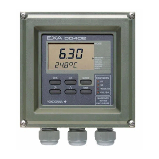
- Page 1 Instruction Model DO402G Converter for Dissolved Oxygen Manual IM 12J6B3-E-H YOKOGAWA 5th Edition...
-
Page 3: Table Of Contents
TABLE OF CONTENTS PREFACE 1. INTRODUCTION AND GENERAL DESCRIPTION ..............1-1 1-1. Instrument check ........................1-1 1-2. Application ........................1-2 1-3. General information........................1-3 1-4. Configuration checklist DO402G....................1-5 1-5. System configuration ........................1-6 1-5-1. Dissolved Oxygen sensor ....................1-6 1-5-2. The holders ........................1-6 2. DO402G SPECIFICATIONS ......................2-1 2-1. - Page 4 7-1. Overall dissolved oxygen metering system................7-1 7-1-1. Inspection and maintenance to be implemented periodically..........7-1 7-1-2. Inspection and maintenance to be implemented on occasion ..........7-1 7-2. Periodic maintenance for the EXA DO402G converter ..............7-2 8. TROUBLESHOOTING........................8-1 8-1. Measures in the case of converter operation failure ..............8-1 8-1-1.
-
Page 5: Preface
Do not use an abrasive or solvent in cleaning the instrument. Notice Contents of this manual are subject to change without notice. Yokogawa is not responsible for damage to the instrument, poor performance of the instrument or losses resulting from such, if the problems are caused by: Improper operation by the user. - Page 6 IM 12J6B3-E-H...
-
Page 7: Introduction And General Description
This instruction manual contains the information needed to install, set up, operate and maintain the unit correctly. This manual also includes a basic troubleshooting guide to answer typical user questions. Yokogawa can not be responsible for the performance of the EXA analyzer if these instructions are not followed. 1-1. Instrument Check Upon delivery, unpack the instrument carefully and inspect it to ensure that it was not damaged during shipment. -
Page 8: Application
For best results, read this manual in conjunction with the corresponding sensor instruction manual. Yokogawa designed and built the EXA to meet the CE regulatory standards. The unit meets or exceeds stringent requirements of EN 55082-2, EN55022 Class A and low voltage safety directive IEC1010 without compromise, to assure the user of continued accurate performance in even the most demanding industrial installations. -
Page 9: General Information
Introduction 1-3 1-3. General information Flexibility, reliability and low maintenance are among the benefits provided by the EXA DO402G dissolved oxygen analyzer. Designed to meet the exacting requirements of measuring dissolved oxygen in the modern industrial environment, it contains many features to ensure the best precision whatever the application. - Page 10 If any of these are outside the limits, an error is signalled. Logbook Software record of important events and diagnostic data. Available through RS485, for use with the Yokogawa PC402 communication software. Serial Communication Bi-directional according to the EIA-485 standard using HART-protocol and PC402 software.
- Page 11 Introduction 1-5 1-4. Configuration checklist for DO402 Standard configuration Options Reference for change Measured variable(s) Primary inputs D.O. and Temp DO range 0- 20 mg/l any span within 0-50 mg/l "range" DO units mg/l ppm. % saturation code 56 Temperature range 0- 50 °C 25 °C minimum span "range"...
-
Page 12: System Configuration
1-5-2. The holders a. PB30 floating ball holder All Yokogawa sensors are compatible with the floating ball holder that is specified in GS12J6K4 and GS12J5A1. b. FD30 immersion fitting The DO30 sensor is compatible with the FD30 immersion holder as specified in GS12J6K4 and with all flow fittings and flow fitting subassemblies that are specified in GS12D7K2. -
Page 13: Do402G Specifications
: The DO402G Dissolved Sensor types: Pt100 or Oxygen converter measures Pt1000 RTD; 2k2 NTC (PB36: the current, that is generated Yokogawa compatible); by the Dissolved Oxygen 22 k NTC (Ingold compatible) sensor. The flexibility of the Automatic or Manual... - Page 14 2-2 Specifications J. Contact outputs - General : Four (4) SPDT relay contacts with LED indicators. For S1, S2, and S3, the LED is on when relay is powered. NOTE: For S4 (FAIL) LED lights when power is removed (Fail safe). Contact outputs configurable for hysteresis and delay time.
-
Page 15: Operating Specifications
Specifications 2-3 2-2. Operating specifications A. Performance : DO (at t process = 25 °C) H. Data protection : ≤ 0.03 mg/l ± 0.02 mA - Linearity : Non volatile memory for : ≤ 0.03 mg/l ± 0.02 mA - Repeatability configuration and logbook, : ≤... - Page 16 IM 12J6B3-E-H...
-
Page 17: Installation And Wiring
Installation and wiring 3-1 3. INSTALLATION AND WIRING 3-1. Installation and dimensions 3-1-1. Installation site The EXA converter is weatherproof and can be installed inside or outside. It should, however, be installed as close as possible to the sensor to avoid long cable runs between sensor and converter. In any case, the cable length should not exceed 50 meters (162 feet). - Page 18 3-2 Installation and wiring wall mounting pipe mounting pipe mounting (vertical) (horizontal) (3.15) 2x ø6,6 (0.26) 4x ø10 (0.4) (5.70) (2.75) 2” ND. pipe OPTION/U: Universal pipe/wall mounting kit Figure 3-3. Wall and pipe mounting diagram Figure 3-4. Internal view of EXA wiring compartment IM 12J6B3-E-H...
-
Page 19: Preparation
Installation and wiring 3-3 3-2. Preparation Refer to figure 3-4. The relay contact terminals and power supply connections are under the screening (shielding) plate. These should be connected first. Connect the sensor, outputs and data communication connections last. To open the EXA 402 for wiring: 1. -
Page 20: Wiring The Power Supply
3-4 Installation and wiring FRONT GLANDS REAR GLANDS Power Sensor Output Contact signals output Contact RS485 output S4/FAIL Contact intput Figure 3-6. System configuration 3-3. Wiring the power supply 3-3-1. General precautions Make sure the power supply is switched off. Also, make sure that the power supply is correct for the specifications of the EXA and that the supply agrees with the voltage specified on the textplate. -
Page 21: Ac Power
After a brief interval, the display will change to the measured value. If errors are displayed or a valid measured value is not shown, consult the troubleshooting section (Chapter 8) before calling Yokogawa. Figure 3-8. Grounding the housing IM 12J6B3-E-H... -
Page 22: Changing The Supply Voltage
3-6 Installation and wiring 3-3-7. Changing the supply voltage To change between the nominal supply voltages 230 and 115 Volts AC it is necessary to solder the appropriate jumpers on the transformer connections. These are located close to the fuse and the power terminals on the power and input board. -
Page 23: Wiring The Analog Output Signals
Installation and wiring 3-7 3-5. Wiring the analog output signals 3-5-1. General precautions The analog output signals of the EXA transmit low power standard industry signals to peripherals like control systems or strip-chart recorders (Figure 3-6). 3-5-2. Analog output signals The output signals consist of active current signals of either 0-20 mA or 4-20 mA. -
Page 24: Wiring Polarographic Sensors
3-8 Installation and wiring 3-8. Wiring polarographic sensors Consult the owners manual for the color identification of the sensor cable and connect temperature compensator, cathode and anode to terminals 11, 12, 17 and 18 in this sequence. Connect the cable shield (when provided) to terminal 14. Figure 3-9. -
Page 25: Operation; Display Functions And Setting
Operation 4-1 4. OPERATION; DISPLAY FUNCTIONS AND SETTING 4-1. Operator interface This section provides an overview of the operation of the EXA operator interface. The basic procedures for obtaining access to the three levels of operation are described briefly. For a step-by-step guide to data entry, refer to the relevant section of this instruction manual. -
Page 26: Explanation Of Operating Keys
MODE mode access key Selection keys WASH/S3 YES : Accept setting Relay contact FAIL/S4 : Change setting status indicators MARKINGS YOKOGAWA WITHIN ENCLOSURE Adjustment keys > : Choose digit to Measure/Maintenance adjust mode key : Adjust digit Broken line indicates area... -
Page 27: Setting Passcodes
Operation 4-3 4-3. Setting passcodes 4-3-1. Passcode protection In Service Code 52, EXA users can set passcode protection for each one of the three operating levels, or for any one or two of the three levels. This procedure should be completed after the initial commissioning (setup) of the instrument. -
Page 28: Display Functions (Default)
AIR.CAL SETPOINTS DISPLAY H2O.CAL RANGE MAN.CAL SET HOLD DISPLAY WASH HOLD SERVICE CONTACTS MODE Current output 1 WASH/S3 FAIL/S4 DISPLAY MARKINGS YOKOGAWA WITHIN ENCLOSURE Current output 2 DISPLAY Press YES to fix the selected second line of display IM 12J6B3-E-H... -
Page 29: Parameter Setting
Parameter setting 5-1 5. PARAMETER SETTING 5-1. Maintenance mode Standard operation of the EXA instrument involves use of the maintenance (or operating) mode to set up some of the parameters. Access to the maintenance mode is available via the six keys that can be pressed through the flexible window in the instrument cover. -
Page 30: Manual Activation Of Hold
SET HOLD WASH SERVICE CONTACTS MODE WASH/S3 FAIL/S4 MARKINGS YOKOGAWA WITHIN ENCLOSURE MODE AIR.CAL HOLD MEASURE Note: The HOLD feature must first be activated in the commissioning mode section 5-2-3. Note: The HOLD feature must first be activated in the commissioning mode section 5.--... -
Page 31: Manual Wash Start/Stop
SETPOINTS RANGE SET HOLD WASH SERVICE CONTACTS MODE WASH/S3 FAIL/S4 MARKINGS YOKOGAWA WITHIN ENCLOSURE MODE MODE AIR.CAL WASH ACTIVE press YES to stop. NOTE: Note: Wash must first be switched on in commissioning mode section 5.5. and set for adjustment in the maintenance mode, by service code 5.1. -
Page 32: Setpoint Adjustment
Setpoints available will depend on their SET HOLD WASH configuration in the Service Code. SERVICE CONTACTS MODE WASH/S3 FAIL/S4 MARKINGS YOKOGAWA WITHIN ENCLOSURE MODE AIR.CAL For adjustments, follow procedures as in section 5-5-1. Setpoint 3 and 4 when enabled in... -
Page 33: Commissioning Mode
Parameter setting 5-5 5-2. Commissioning mode In order to obtain peak performance from the EXA converter, you must set it up for each custom application. Refer to section 1-4 for standard configurations and options. Setpoints Alarms are set by default S1 - high process alarm S2 - low process alarm S3 - WASH... -
Page 34: Setpoints
5-6 Parameter setting 5-2-1. Setpoints MODE MEASURE AIR.CAL SETPOINTS H2O.CAL RANGE MAN.CAL SET HOLD DISPLAY WASH HOLD SERVICE repeated keystrokes IM 12J6B3-E-H... - Page 35 Parameter setting 5-7 Process Alarms on S.3 and S.4 are only available when enabled in Service Codes 40-49 Analogue control setpoint is only available when enabled in Service Code 31 Adjust setpoint value using > ENT keys as shown for setpoint 1. Setpoint confirmed- return to commissioning menu.
-
Page 36: Range
5-8 Parameter setting 5-2-2. Range MODE MEASURE AIR.CAL SETPOINTS H2O.CAL RANGE MAN.CAL SET HOLD DISPLAY WASH HOLD SERVICE See facing page IM 12J6B3-E-H... - Page 37 Parameter setting 5-9 Choose Range to adjust, then set begin scale (0%) and end scale (100%) of the mA output signal, using the >, ,and ENT keys. Selection of mA output (0-20 / 4-20 mA) is in Service Code 30. Note: Range 2 does not appear Note: Range 2 does not Range Selection Options...
-
Page 38: Hold
5-10 Parameter setting 5-2-3. Hold MODE MEASURE AIR.CAL SETPOINTS H2O.CAL RANGE MAN.CAL SET HOLD DISPLAY WASH HOLD SERVICE HOLD deactivated, return to commissioning menu. HOLD HOLD active last measured value. IM 12J6B3-E-H... - Page 39 Parameter setting 5-11 HOLD values set, return to commissioning menu. HOLD HOLD HOLD HOLD Set HOLD "fixed value" HOLD for mA2. HOLD Set HOLD "fixed value" for mA1. IM 12J6B3-E-H...
-
Page 40: Wash
5-12 Parameter setting 5-2-4. Wash MODE (NOTE: The menu item "WASH" will not appear unless selected in Service Code 42) MEASURE AIR.CAL SETPOINTS H2O.CAL RANGE MAN.CAL SET HOLD DISPLAY WASH HOLD SERVICE Wash system timings are set with the >, , and ENT keys in the setpoint menu IM 12J6B3-E-H... -
Page 41: Service
Parameter setting 5-13 5-2-5. Service NOTE: MODE For information on how to set cell current, see description in Section 1-5, A4 MEASURE AIR.CAL SETPOINTS RANGE H2O.CAL MAN.CAL SET HOLD DISPLAY WASH HOLD SERVICE Example: Service Code 01 Select Sensor Type for galvanic sensor Nominal cell current at 100% Saturation. -
Page 42: Notes For Guidance In The Use Of Service Coded Settings
Select 0 for SM31 sensor with a nominal cell current of 50 nA. Select 9 for other polarographic sensor, with the nominal cell current to be user defined. General Note: Dissolved oxygen sensors fall into two categories – galvanic and polarographic. Yokogawa offer both types: Settings for Yokogawa Sensors DO30 DO30 SM31. - Page 43 Parameter setting 5-15 Code Display Function Function detail Default values Parameter Specific functions *S. TYPE Sensor type Galvanic Polarographic *I CELL Sensor output 3.75 µA for 50 micron type Galvanic 7.50 µA for 25 micron type User defined 3.75 µA *I CELL Sensor output 50 nA...
-
Page 44: Temperature Functions
5-16 Parameter setting 5-3-2. Temperature functions Code 10 *T.SENS Select temperature sensor to suit the measuring probe. Refer to instructions with DO sensor for which temperature sensor is used. Code 11 *T.UNIT Select °C or °F for temperature display. Code 12 *T.ADJ. - Page 45 Parameter setting 5-17 Code Display Function Function detail Default values Temperature Measuring Functions *T.SENS Temp. Comp. Pt100 RTD Pt1000 RTD PB36 = 2k2 NTC (DO30) 22k NTC (SM31) *T.UNIT Temp units Celsius Fahrenheit *T.ADJ Temp adjust Adjustment +/- 7.5 °C or +/- 13.5 °F *T.MAN Manual TC Automatic temperature comp...
-
Page 46: Calibration Functions
5-18 Parameter setting 5-3-3. Calibration functions Code 20 *∆T.SEC Set stability parameters for calibration. A greater time, and/or a smaller step gives *∆mg/l greater stability before a calibration can be accepted. Use caution, however, to avoid very long calibration times. Code 21 *0.CAL Not normally necessary, zero calibration can be enabled when required. - Page 47 Parameter setting 5-19 Code Display Function Function detail Default values Calibration Settings *∆T.SEC Stabilization Stabilisation time range 10- 600 s 60 s *∆mg/l Step DO step change range 0-50 mg/l 0.05 mg/l or 0-300 % *0.CAL Zero cal. Zero calibration disabled Zero Calibration enabled *ZERO Zero entry...
-
Page 48: Ma Output Settings
5-20 Parameter setting 5-3-4. mA output settings Code 30 Select 0-20 mA or 4-20 mA for each of the mA outputs. Code 31 *OUTP.F Select the parameter to be transmitted on each of the mA outputs. *D/R Select the control action when PI selected on mA2. Direct action gives an increasing output with an increase in measured value. - Page 49 Parameter setting 5-21 Code Display Function Function detail Default values mA Output Functions mA output Output 1 is 0- 20 mA Output 1 is 4- 20 mA Output 2 is 0- 20 mA Output 2 is 4-20 mA *OUTP.F Output function Process value on mA1 Table on mA1 Process value on mA2...
-
Page 50: Contact Outputs
5-22 Parameter setting 5-3-5. Contact outputs Code 40, *S1 & *S2 Process relays can be set for a variety of alarm and control function. 41, 42 & 43 Digit "X" sets the type of trigger: Off means that the relay is not active Low setpoint means that the relay is triggered by a decreasing measurement. - Page 51 Parameter setting 5-23 Code Display Function Function detail Default values Contact Settings *S 1 Contact S1 Contact 1 inactive 2.0.0 Low alarm configuration High alarm configuration Active during HOLD Activation by process value Proportional duty cycle Proportional pulse frequency Activation by temperature PI control inactive PI control active * S 2...
- Page 52 5-24 Parameter setting Code 44 *D.TIME The delay time (or dead time) sets the minimum relay switching time. This function can be adjusted to give a good alarm function in a noisy process, preventing the relay from "chattering" or repeatedly switching when the signal is close to the setpoint.
- Page 53 Parameter setting 5-25 Code Display Function Function detail Default values Contacts Settings *D.TIME Dead Time Delay after setpoint passed 0- 2.0 s 0.2 s *P.HYST Hysteresis Process value hysteresis 0-50 mg/l or 0-300 % 0.1 mg/l *T.HYST Temp hyst Temperature hysteresis 0- 5 °C (0- 10 °F) 0.5 °C *RANGE...
-
Page 54: User Interface
5-26 Parameter setting 5-3-6. User interface Code 50 *RET. When Auto return is enabled, the converter reverts to the measuring mode from anywhere in the configuration menus, when no button is pressed during the set time interval of 10 minutes. Code 51 *MODE The adjustment of the contact setpoints, and the manual operation of the wash... - Page 55 Parameter setting 5-27 Code Display Function Function detail Default values User Interface *RET Auto return No return to meas. from HOLD Return to meas after 10 min *MODE add. to MAINT Setpoint adj. disabled 0.0.0 Setpoint adj. also in MAINT Wash start disabled Wash start in maintenance mode Manual pressure disabled...
-
Page 56: Communication Setup
The settings should be adjusted to suit the communicating device connected to the RS485 port. *SET. *ADDR. For the Yokogawa PC402 software package, the default settings match the software as shipped. Code 61 *HOUR The clock/calendar for the logbook is set for current date and time as reference. - Page 57 Parameter setting 5-29 Code Display Function Function detail Default values Communication *COMM. Communication Set communication Set communication Communication write enable write Communication write protect protect *SET. Baud rate & parity Baud rate 1200 2400 4800 9600 9600 Parity Even *ADDR. Network address Set address 00 to 15 *HOUR...
-
Page 58: Test And Setup Mode
5-30 Parameter setting 5-3-9. Test and setup mode Code 80 *TEST The test mode is used to confirm the instrument setup. It is based on the factory setup procedure and can be used to check the QIC (factory generated test certificate). - Page 59 Parameter setting 5-31 Code Display Function Function detail Default values Test and setup mode *TEST Test and setup Built in test functions as detailed in QIS and Service Manual IM 12J6B3-E-H...
- Page 60 IM 12J6B3-E-H...
-
Page 61: Calibration
Calibration 6-1 6. CALIBRATION PROCEDURE Calibration of the dissolved oxygen analyzer is performed in the following situations: • When a new dissolved oxygen sensor is installed. • When the membrane is replaced and/or the electrolyte solution is replaced • When the sensor has been disassembled and reassembled for maintenance •... -
Page 62: Diagnostic Functions Performed During Calibration
6-2 Calibration 6-1-2. Diagnostic functions performed during calibration The calibration is a semi-automatic calibration, which means that the sensor output is used for calculation of sensor parameters after the readings have stabilized. The criteria for stabilization are set in service code 20. If stable readings are not achieved within one hour error E1 message will appear on the display and the procedure is aborted. -
Page 63: Procedure For Air Calibration
AIR.CAL H2O.CAL MAN.CAL DISPLAY HOLD CONTACTS MODE WASH/S3 FAIL/S4 YOKOGAWA The instruments waits for the reading to stabilise. (The display flashes) When reading Is stable, the CAL END message appears. Press YES for single point adjustment. After briefly displaying WAIT, the display returns to the normal readout. -
Page 64: Calibration Procedure Using Water Calibration Method
6-4 Calibration 6-3. Calibration procedure using water calibration method 6-3-1. Preparation Move the sensor to a maintenance site and wash off any dirt on the membrane. Lightly wipe off any remaining water from the membrane with a soft tissue. Prepare the necessary equipment and reagents to be used for the span and (if required) zero calibration. Equipment for span calibration includes: •... -
Page 65: Procedure For Water Calibration
DISPLAY HOLD Place sensor in calibration solution CONTACTS MODE WASH/S3 FAIL/S4 YOKOGAWA The instruments waits for the reading to stabilize. (The display flashes) When reading Is stable, the CAL.END message appears. Note: To start calibration with a zero solution, press... -
Page 66: Preparation
6-6 Calibration 6-4. Calibration method using manual calibration method 6-4-1. Preparation a. Cleaning Confirm that the readings of the analyzer are stable and measured with a clean sensor. Otherwise move the sensor to a maintenance site and wash off any dirt on the sensor membrane Move the sensor back to the process water and wait for the readings to stabilize. -
Page 67: Procedure For Manual Calibration
DISPLAY HOLD CONTACTS MODE WASH/S3 FAIL/S4 YOKOGAWA After briefly displaying WAIT, the display returns to the normal readout. Select the flashing digit with the > key. Increase its value by pressing the key. When the correct value is displayed, press ENT to enter the change. - Page 68 6-8 Calibration Table 6-1. Solubility of oxygen (mg/l) in water as a function of temperature & salinity Temp Solubility of oxygen in water in equilibrium Correction to be substracted for each degree of salinity with air expressed in grams per kilogram of total salts in water @101.325kPa[pO [∆pO °C...
-
Page 69: Maintenance
Maintenance 7-1 7. MAINTENANCE It is important for maintaining the measurement accuracy of the EXA DO series of wire dissolved-oxygen metering system to perform inspection and maintenance at fixed intervals. It also serves to prevent problems from arising. This chapter describes daily inspection and maintenance for the purpose of maintaining system performance. -
Page 70: Periodic Maintenance For The Exa Do402G Converter
7-2 Maintenance 7-2. Periodic maintenance for the EXA DO402 converter The DO402 transmitter requires very little periodic maintenance. The housing is sealed to IP65 (NEMA 4X) standards, and remains closed in normal operation. Users are required only to make sure the front window is kept clean in order to permit a clear view of the display and allow proper operation of the pushbuttons. -
Page 71: Troubleshooting
If the operation keys do not operate smoothly or the display fails (e.g., a missing character segment), repair of the printed circuit board (digital board) (replacement with a new one) is required. After the printed circuit board is replaced, operation checks and parameter settings are necessary. Contact Yokogawa and request board-replacement work. IM 12J6B3-E-H... -
Page 72: Measures In The Case Of Failure (Error) Detection
8-2 Troubleshooting 8-2. Measures in the case of failure (Error) detection If a failure is detected through the self-diagnosis of the DO402 dissolved-oxygen converter, the FAIL contact is closed. The FAIL lamp on the operation panel lights up and an error number appears in the data display. NOTE: If an error is detected during configuration, the FAIL contact signal is output immediately but the error number is displayed after that action or operation is completed. - Page 73 Re-enter a value within the permissible A value not within the permissible range range. is entered. All modes Instrument initialization failure Repair is necessary. Contact Yokogawa to request repair. All modes EPROM comparison failure Repair if necessary. Contact Yokogawa to request repair.
- Page 74 IM 12J6B3-E-H...
-
Page 75: Spare Parts
Pipe and wall mounting hardware K1542KW Panel mounting hardware K1541KR /SCT Stainless steel tag plate K1543ST * NOTE: Contact your local Yokogawa service centre for the procedures for changing items 2 and 5. (Re-initialization of the instrument). Fig. 9-1. Exploded view IM 12J6B3-E-H... - Page 76 IM 12J6B3-E-H...
-
Page 77: Appendix
Appendix 10-1 10. APPENDIX Adjustable limits and defaults for settings in Commissioning Level 10-1. Setpoint Variable Default Lower limit Upper limit *OX1 19.5 mg/l 0.0 mg/l 50.0 mg/l 0.0 ppm 50.0 ppm 0.0 %sat 300 %sat *OX2 1.0 mg/l 0.0 mg/l 50.0 mg/l 0.0 ppm 50.0 ppm... -
Page 78: User Setting Table
10-2 Appendix 10-5. User setting table FUNCTION SETTING DEFAULTS USER SETTINGS Parameter specific functions *S.TYPE Galvanic (7 µA) *I.CELL 3.75 µA *CHECK 0.1.0 Zero Off Slope On Membrane Off *SAL.TY Temperature measuring functions *T.SENS Pt1000 *T.UNIT °C *T.ADJ None *T.MAN Calibration parameter functions *∆T.SEC sec. - Page 79 Appendix 10-3 FUNCTION SETTING DEFAULTS USER SETTINGS User Interface *RET *MODE 0.00 off.off, off *PASS 0.0.0 all off *Err.01 hard fail *Err.02 hard fail *Err.03 hard fail *Err.04 hard fail *Err.07 hard fail *Err.08 hard fail *Err.09 hard fail *Err.12 hard fail *Err.16 soft fail...
- Page 80 10-4 Appendix 10-6. Software Revision History Software changes of the DO402 10-6-1. Changes made by software release 1.1 Slope calculation bug is solved in release 1.1. In release 1.0 calibration caused a wrong slope calculation, resulting in a wrong measurement. The Air calibration menu in the maintenance mode is expanded with a zero current (0%) calibration, used for calibration in nitrogen.
-
Page 81: Error Codes
Wrong data programmed Reprogram Programmed values outside acceptable limits Incorrect configuration by user Reprogram All programmed data lost Fault in electronics Contact Yokogawa Very severe interference Checksum error Software problem Contact Yokogawa Alarm activation time exceeded Process control not effective... - Page 82 Vélizy Valley Vicolo D. Pantaleoni, 4 SINGAPORE 20161 MILANO THE NETHERLANDS 18-20 Rue Grange Dame Rose Yokogawa Engineering Asia Pte. Ltd. 78140 VELIZY VILLACOUBLAY Tel. +39-02-66 24 11 Yokogawa Nederland B.V. 11, Tampines Street 92 Fax +39-02-645 57 02 Hoofdveste 11 Tel.
Need help?
Do you have a question about the EXA DO402G and is the answer not in the manual?
Questions and answers