Table of Contents
Advertisement
Quick Links
Download this manual
See also:
User Manual
Advertisement
Table of Contents

Related Manuals for YOKOGAWA EXA DO402G


Summary of Contents for YOKOGAWA EXA DO402G
- Page 1 User’s Manual Model DO402G Dissolved Oxygen Converter [Style: S3] IM 12J05D02-01E IM 12J05D02-01E 9th Edition...
-
Page 2: Introduction
Do not use an abrasive or solvent in cleaning the instrument. Yokogawa is not responsible for damage to the instrument, poor performance of the instrument or losses resulting from such, if the problems are caused by: • Improper operation by the user. -
Page 3: Safety Precautions
• If this instrument is used in a manner not specified in this user’s manual, the protection provided by this instrument may be impaired. • If any protection or safety circuit is required for the system controlled by the product or for the product itself, prepare it separately. • Be sure to use the spare parts approved by Yokogawa Electric Corporation (hereafter simply referred to as YOKOGAWA) when replacing parts or consumables. • Modification of the product is strictly prohibited. • The following safety symbols are used on the product as well as in this manual. WARNING This symbol indicates that an operator must follow the instructions laid out in this manual in order to avoid the risks, for the human body, of injury, electric shock, or fatalities. -
Page 4: Warranty And Service
Some screen images depicted in the user’s manual may have different display positions or character types (e.g., the upper / lower case). Also note that some of the images contained in this user’s manual are display examples. Warranty and service Yokogawa products and parts are guaranteed free from defects in workmanship and material under normal use and service for a period of (typically) 12 months from the date of shipment from the manufacturer. Individual sales organisations can deviate from the typical warranty period, and the conditions of sale relating to the original purchase order should be consulted. - Page 5 In the event of warranty claim, the defective goods should be sent (freight paid) to the service department of the relevant sales organisation for repair or replacement (at Yokogawa discretion). The following information must be included in the letter accompanying the returned goods: • Part number, model code and serial number • Original purchase order and date • Length of time in service and a description of the process • Description of the fault, and the circumstances of failure • Process/environmental conditions that may be related to the failure of the device. • A statement whether warranty or nonwarranty service is requested • Complete shipping and billing instructions for return of material, plus the name and phone number of a contact person who can be reached for further information.
-
Page 6: Table Of Contents
Toc-1 Model DO402G Dissolved Oxygen Converter [Style: S3] IM 12J05D02-01E 9th Edition TABLE OF CONTENTS Introduction ....................i Safety Precautions ..................ii Introduction and General Description ........... 1-1 Instrument Check ....................1-1 Application ......................1-2 General information ..................1-3 1.4 Configuration checklist for DO402 ..............1-6 1.5 System Configuration .................. - Page 7 Toc-2 3.5.2 Analog output signals ............... 3-12 Wiring the standard galvanic sensor ............3-12 Wiring other galvanic sensors ..............3-13 Wiring the standard optical sensor (DO70G) ..........3-14 Wiring polarographic sensors ............... 3-16 3.10 Wiring RS-485 signal ..................3-16 Operation; Display Functions And Setting ..........4-1 Operator interface .....................
- Page 8 Inspection and maintenance to be implemented periodically ... 7-1 7.1.2 Inspection and maintenance to be implemented on occasion ..7-1 Periodic maintenance for the EXA DO402G converter ......... 7-2 Fuse Replacement .................... 7-2 Troubleshooting ..................8-1 Measures in the case of converter operation failure ........8-1 8.1.1...
- Page 9 Blank Page...
-
Page 10: Introduction And General Description
This manual also includes a basic troubleshooting guide to answer typical user questions. Yokogawa can not be responsible for the performance of the EXA analyzer if these instructions are not followed. -
Page 11: Application
The measurement can be used as part of an automated process control system. It can also be used to indicate dangerous limits of a process, to monitor product quality, or to function as a simple controller for a dosing/neutralization system. Yokogawa designed the EXA analyzer to withstand harsh environments. The converter may be installed either indoors or outside because the IP65 (NEMA 4X) housing and cabling glands ensure the unit is adequately protected. The flexible polycarbonate window on the front door of the EXA allows pushbutton access to the keypad, thus preserving the water and dust protection of the unit even during routine maintenance operations. -
Page 12: General Information
<1. Introduction and General Description> General information Flexibility, reliability and low maintenance are among the benefits provided by the EXA DO402G dissolved oxygen analyzer. Designed to meet the exacting requirements of measuring dissolved oxygen in the modern industrial environment, it contains many features to ensure the best precision whatever the application. This 4-wire converter is housed in a robust IP65 field mountable case. Two mA outputs, four relays, digital communication and a clear LCD make the DO402G a truly comprehensive package. - Page 13 <1. Introduction and General Description> The DO70G sensor operates based on the principle of optical (fluorescence) measurement. The sensor comprises a fluorescent membrane, light-emitting part, light-receiving part, and internal circuit. An external power source is required. Oxygen molecules pass through the permeable membrane to a fluorescent substance and shift the phase of fluorescent emission. The degree of this shift is inversely proportional to the partial pressure of oxygen on the sample side, resulting in the output of a current equivalent to the polarographic current adjusted by the internal circuit. A temperature sensor is integrated in both sensors, and the temperature signals are used to automatically compensate the measurements of dissolved oxygen.
- Page 14 If any of these are outside the limits, an error is signalled. Logbook Software record of important events and diagnostic data. Available through RS-485, for use with the Yokogawa PC402 communication software. Serial Communication Bi-directional according to the EIA-485 standard using HART-protocol and PC402 software. IM 12J05D02-01E 9th Edition: Aug. 05, 2015-00...
-
Page 15: Configuration Checklist For Do402
<1. Introduction and General Description> 1.4 Configuration checklist for DO402 Standard configuration Options Reference for change Measured variable(s) Primary inputs D.O. and Temp DO range 0- 20 mg/L any span within 0-50 mg/L “range” DO units mg/L ppm. % saturation code 56 Temperature range 0- 50 °C 25 °C minimum span “range” Temperature unit Celsius Fahrenheit code 11... -
Page 16: System Configuration
<1. Introduction and General Description> 1.5 System Configuration Dissolved Oxygen Converter Holders, Holders with Cleaning System Dissolved Oxygen Sensor ● DO402G ● Floating Ball Holder Output Signal: ● Guide Pipe ● DO70G 4 to 20 m A DC or PH8HG PB350G PB360G 0 to 20 m A DC Alarm Contact Output... -
Page 17: The Holders
The white wire: the cathode goes to terminal 17 The green/yellow wire: the shield goes to terminal 14 and the 2 black wires for NTC go to terminal 11 and 12. The membrane checking feature cannot be used for these sensors, due to the construction of the sensor. 1.5.2 The holders l PB30 floating ball holder All Yokogawa sensors are compatible with the floating ball holder that is specified in GS 12J6K4- E-E and GS 12J5A1. l FD30 immersion fitting The DO30 sensor is compatible with the FD30 immersion holder as specified in GS 12J6K4-E-E and with all flow fittings and flow fitting subassemblies that are specified in GS 12D7K2. DOX8HS submersion type holder The DOX8SM and the DO30G sensor are compatible with the DOX8HS holder and all PH8 model holders. -
Page 18: Do402G Specifications
Output Signals Two isolated outputs of 0/4- 20 mA DC with common negative. Maximum load 600 Ohm. Auxiliary output can be chosen from Temperature, DO, PI control, table, burn up (22 mA) or burn down (0 or 3.5 mA) to signal failure Temperature compensation 0 to 50 ºC Sensor types: P t100 or Pt1000 RTD; PB36 (Yokogawa compatible); 22 k NTC (Ingold compatible) Automatic or Manual temperature compensation Calibration Semi-automatic calibration with automatic compensation for influence of barometric pressure and altitude on partial pressure of oxygen in air (or solubility of oxygen in water). Automatic compensation for influence of salinity of water on solubility of oxygen in water is programmable. The correction for pressure, salinity and temperature meets ISO 5814 Possible calibration routines are: S lope (span) calibration in ambient air. The calibration table is based on 70 % RH and is... -
Page 19: Power Supply
<2. DO402G Specifications> Serial Communication Bi-directional according to the EIA-485 standard using HART protocol and PC402 software. Logbook Software record of important events and diagnostic data. Available through RS-485, with key diagnostic information available in the display. Display Custom liquid crystal display, with a main display of 3 1/2 digits 12.5 mm high. Message display of 6 alphanumeric characters, 7 mm high. Contact outputs General: F our (4) SPDT relay contacts with LED indicators. For S1, S2, and S3, the LED is on when relay is powered. NOTE: For S4 (FAIL) LED lights when power is removed (Fail safe). Contact outputs configurable for hysteresis and delay time. - Capacity : Maximum values 100 VA, 250 V AC, 5 Amps. - Page 20 <2. DO402G Specifications> Safety and EMC conforming standards Safety: conforms to EN 61010-1 EN 61010-2-030 CAN/CSA No.61010-1 UL Std. No. 61010-1 CSA C22.2 No. 94.2 UL 50E EMC: EN 61326-1* Class A, Table 2 (For use in industrial locations) (Note 1) EN 61326-2-3 EN 61000-3-2 Class A EN 61000-3-3 EMC Regulatory Arrangement in Australia and New Zealand EN 55011 Class A, Group 1 Korea Electromagnetic Conformity Standard Class A 한국 전자파적합성 기준 *: Influence of immunity environment (Criteria A): Output shift is specified within ±25% of F.S. Installation altitude: 2000 m or less Category based on IEC 61010: II (Note 2) Pollution degree based on IEC 61010:2 (Note 2) Note 1: This instrument is a Class A product, and it is designed for use in the industrial environment.
-
Page 21: Operating Specifications
<2. DO402G Specifications> 2.2 Operating specifications Performance : DO (at t process = 25 °C) Linearity: ± 0.03 mg/L or ± 0.5%FS, whichever is greater Repeatability: ± 0.03 mg/L or ± 0.5%FS, whichever is greater Accuracy: ± 0.05 mg/L or ± 0.5%FS, whichever is greater Performance : Temperature (Pt1000, PB36, 22kNTC) Linearity: ± 0.3 ºC Repeatability: ± 0.1 ºC Accuracy: ± 0.3 ºC Performance : Temperature (Pt100) Linearity: ± 0.4 ºC Repeatability: ±... -
Page 22: Model And Suffix Codes
<2. DO402G Specifications> Watchdog timer Checks microprocessor Automatic safeguard Return to measuring mode when no keystroke is made for 10 min. Power interruption Less than 50 milliseconds no effect. Operation protection 3-digit programmable password. 2.3 Model and suffix codes [Style: S3] Model Suffix code Option code Description DO402G •••••••••••••••••• ••••••••••••••••• Dissolved Oxygen Converter Type •••••••••••••••••... - Page 23 Blank Page...
-
Page 24: Installation And Wiring
<3. Installation and Wiring> Installation and Wiring Installation and dimensions CAUTION Installation must be performed by a qualified personnel. If this rules is not followed and a damage occurs, Yokogawa will not be held responsible. 3.1.1 Installation site CAUTION This instrument is a Class A product, and it is designed for use in the industrial environment. - Page 25 <3. Installation and Wiring> Unit: mm (inch) Hood (optional) □ Option code : /H Four M6 screws, 8 deep (0.31) (7.24) (8.66) (3.15) (2.83) (0.79) (5.67) (3.15) (4.41) Adaptor for conduit work (5.67) (0.91) (option code : /AFTG, /ANSI) Cable inlet port (Six-21 dia.
- Page 26 <3. Installation and Wiring> Example of bracket used for pipe mounting M6, 4 screws * (7.40) (6.85) (7.87) (1.97) Nominal 50A (O.D 60.5mm) mounting pipe (3.94) Example of bracket used for wall mounting M6, 4 screws * (5.31) (0.51) (8.82) (7.87) (1.38) (0.59)
-
Page 27: Wiring
<3. Installation and Wiring> Wiring CAUTION Wiring must be performed by a qualified personnel. If this rules is not followed and a damage occurs, Yokogawa will not be held responsible. 3.2.1 Wiring of DO30G DO402G Output signal (4 to 20mA DC or 0 to 20mA DC) Power supply mA 1 Output signal mA 2 Contact (4 to 20mA DC or 0 to 20mA DC) -
Page 28: Wiring Of Do70G
<3. Installation and Wiring> 3.2.2 Wiring of DO70G DO402G Output signasl 61 + (4 to 20mA DC or 0 to 20mA DC) 62 ‒ Power supply Output signal 65 + (4 to 20mA DC or 66 ‒ 0 to 20mA DC) Contact signal S1 High and Low alarms... -
Page 29: Preparation
<3. Installation and Wiring> 3.2.3 Preparation The relay contact terminals and power supply connections are under the screening (shielding) plate. These should be connected first. Connect the sensor, outputs and data communication connections last. Follow the procedures below to open the DO402G for wiring: Loosen the four frontplate screws and remove the cover. Use the rubber knob in the lower right hand corner and swing open the display board to the left. The upper terminal strip is now visible. Remove the screen (shield) plate covering the lower terminal strip. Connect the power supply and contact outputs. Use the three glands at the back for these cables. Replace the screen (shield) plate over the lower terminals. WARNING Always replace the screen plate over the power and contact outputs for safety and to avoid interference. -
Page 30: Wiring The Power Supply
<3. Installation and Wiring> Wiring the power supply 3.3.1 General precautions Make sure the power supply is switched off. Also, make sure that the power supply is correct for the specifications of the EXA and that the voltage specified on the nameplate on the left side of the DO402G is satisfied. Local health and safety regulations may require an external circuit breaker to be installed. The instrument is protected internally by a fuse. The fuse rating is dependent on the supply to the instrument. The 250 VAC fuses should be of the “time-lag” type, conforming to IEC60127. - Page 31 <3. Installation and Wiring> High Voltage Section POWER CABLE SENSOR CABLE (S) ANALOG OUTPUTS for DO70G or CABLE COMMUNICATION INPUT CONTACT *1 CONTACT (S3, S4/FAIL) CONTACT (S1, S2) POWER CABLE OUTPUT CABLE (S) OUTPUT CABLE (S) Suitable for cables with an outside diameter between 6 - 12 mm (0.24 - 0.47 in.) *1: Use D or E for cable gland of DO70G power cable when both DO70G and contact input are used.
-
Page 32: Grounding The Housing
<3. Installation and Wiring> Contact Digital Sensor Inputs mA Outputs Input Communications 17 11 63 66 65 62 61 95 94 93 92 91 Liquid SCREEN earth Shield SCREEN SCREEN Temp SCREEN 2 CONT SENSOR mA OUTPUT RS485 - - - optical sensor and polarographic sensor galvanic sensor Relay Contacts Power Supply... -
Page 33: Switching On The Instrument
Make sure the LCD display comes on. All segments will illuminate, then the instrument will momentarily display its unique serial number. After a brief interval, the display will change to the measured value. If errors are displayed or a valid measured value is not shown, consult the troubleshooting section (Chapter 8) before calling Yokogawa. Wiring the contact signals WARNING There are high-voltage sections on the EXA. Be sure to turn off the power before wiring. -
Page 34: Contact Input
3-11 <3. Installation and Wiring> Default settings • The contact S1 is pre-programmed for high alarm function. • The contact S2 is pre-programmed for a low alarm function. • The contact S3 is pre-programmed for wash function. • The contact S4 is pre-programmed for FAIL. The three control contacts (S1 to S3) can be used for simple process control by programming their function (Chapter 5). The FAIL contact is programmed to signal a fault in the measuring loop. Always connect the FAIL contact to an alarm device such as a warning light, sound annunciator, or alarm panel to make full use of the fault detection possibilities (self diagnostics) of the EXA converter. When using ON/OFF signals whose voltage is 3.3 VAC or 70 VDC or higher, use 2.5 mm (AWG14) wires. If using voltages lower these voltages, select wires in the range of 0.13 to 2.5 (AWG26 to AWG14) according to the current capacity of the connected load. Use cables that comply with UL2556VM-1 or equivalent and whose outer diameter is 6 to 12 mm. Tighten the cables to 0.5 N•m torque. 3.4.3 Contact input Voltage-free contact (do not apply voltage) Wash start or input remote range change (either choice) It is necessary to use screening/shielding on the output signal cables. Screw (M3) 23 is used to connect the shielding. On resistance: 10 Ω or less Off resistance: 100 kΩ or more Select wires in the range of 0.13 to 2.5 mm (AWG26 to AWG14) according to the current capacity of the connected load. -
Page 35: Analog Output Signals
3-12 <3. Installation and Wiring> 3.5.2 Analog output signals The output signals consist of active current signals of either 0-20 mA or 4-20 mA. The maximum load can be 600 ohms on each. It should be necessary to use screening/shielding on the output signal cables. Terminal 63 is used to connect the shielding. Figure 3.11 Cable gland assembly Wiring the standard galvanic sensor Do not use cables other than the dedicated cables. -
Page 36: Wiring Other Galvanic Sensors
3-13 <3. Installation and Wiring> The overall shield of the cable is marked with 14 and must be connected to terminal 14. CAUTION A jumper cable is placed to connect converter terminals 13 and 17. Make sure that connecting the sensor cable to the IE pin or pin 13 or pulling the sensor cable does not cause the jumper cable to come loose. Insufficient tightening may cause unstable or false measurements. -
Page 37: Wiring The Standard Optical Sensor (Do70G)
3-14 <3. Installation and Wiring> Wiring the standard optical sensor (DO70G) NOTE A jumper cable is placed to connect converter terminals 13 and 17. When a standard optical sensor (DO70G) is to be connected, the cable is not used, so disconnect it. It is recommended to save the jumper cable for future use—if may be needed when a galvanic sensor is used. - Page 38 3-15 <3. Installation and Wiring> DO70G Wiring Diagram Example DOX10 DO402G Detail-1 Detail-2 DO70G Detail-2(DOX10) Connections of the sensor cable and DOX10 terminals are shown in the following table. Detail-1(DO402G) DO70G (Wiring color) DOX10 (terminal No.) Connections of the sensor cable and DO402G BROWN + BROWN terminals are shown in the following table.
-
Page 39: Wiring Polarographic Sensors
3-16 <3. Installation and Wiring> Wiring polarographic sensors Consult the owners manual for the color identification of the sensor cable and connect temperature compensator, cathode and anode to terminals 11, 12, 17 and 18 in this sequence. Connect the cable shield (when provided) to terminal 14. CAUTION A jumper cable is placed to connect converter terminals 13 and 17. When a polarographic sensor is to be connected, the cable is not used, so disconnect it. It is recommended to save the jumper cable for future use—if may be needed when a galvanic sensor is used. -
Page 40: Operation; Display Functions And Setting
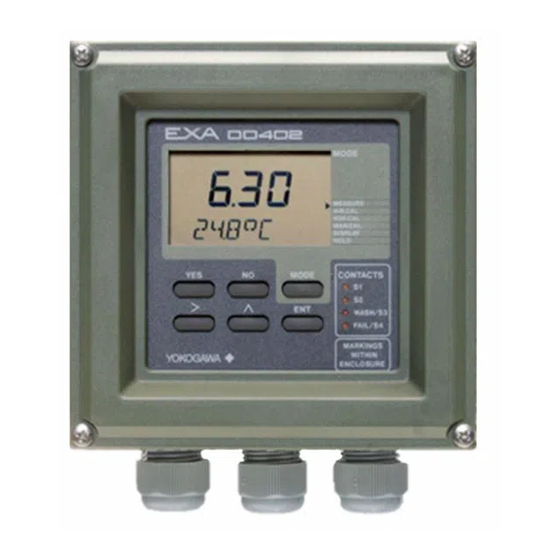
<4. Operation; Display Functions And Setting> Operation; Display Functions And Setting Operator interface This section provides an overview of the operation of the EXA operator interface. The basic procedures for obtaining access to the three levels of operation are described briefly. For a step- by-step guide to data entry, refer to the relevant section of this instruction manual. Figure 4.1 shows the EXA operator interface. -
Page 41: Explanation Of Operating Keys
Relay contact Yes: Accept setting WASH/S3 status indicators No: Change setting FAIL/S4 Measure/Maintenance MARKINGS Adjustment keys YOKOGAWA WITHIN mode key ENCLOSURE Choose digit to adjust Broken line indicates area Adjust digit ENT: Confirm change that can be seen through front cover Figure 4.1 DO402 operator interface... -
Page 42: Setting Passcodes
<4. Operation; Display Functions And Setting> Setting passcodes In Service Code 52, EXA users can set passcode protection for each one of the three operating levels, or for any one or two of the three levels. This procedure should be completed after the initial commissioning (setup) of the instrument. The passcodes should then be recorded safely for future reference. -
Page 43: Display Functions (Default)
<4. Operation; Display Functions And Setting> Display functions (default) Display Access MEASURE AIR.CAL H2O.CAL DISPLAY MAN.CAL Cell current DISPLAY HOLD MODE (See Air AIR.CAL calibration DISPLAY Slope Chapter 6) (See H Zero calibration, calibration when enabled Chapter 6) in service code 51 H2O.CAL DISPLAY (See Manual... -
Page 44: Parameter Setting
<5. Parameter setting> Parameter setting Maintenance mode Standard operation of the EXA instrument involves use of the maintenance (or operating) mode to set up some of the parameters. Access to the Maintenance mode is available via the six keys that can be pressed through the flexible window in the instrument cover. Press the MODE key once to enter this dialog mode. Note : At this stage the user will be prompted for pass code where this has been previously set up in service code 52 in chapter 5. -
Page 45: Manual Activation Of Hold
RANGE SET HOLD WASH SERVICE CONTACTS MODE WASH/S3 FAIL/S4 MARKINGS YOKOGAWA WITHIN ENCLOSURE MODE AIR.CAL HOLD MEASURE Note: The HOLD feature must first be activated in the commissioning mode section 5.2.3. Refer to note of section 5.2.3. Hold also. IM 12J05D02-01E... -
Page 46: Manual Wash Start/Stop
RANGE SET HOLD WASH SERVICE CONTACTS MODE WASH/S3 FAIL/S4 MARKINGS YOKOGAWA WITHIN ENCLOSURE MODE MODE AIR.CAL WASH ACTIVE press YES to stop. Note: Relay S3 must first be set for “WASH” in service code 42. Manual wash start/stop is enabled with Service code 51. -
Page 47: Setpoint Adjustment
Setpoints available will depend on their SET HOLD WASH configuration in the Service Code. SERVICE CONTACTS MODE WASH/S3 FAIL/S4 MARKINGS YOKOGAWA WITHIN ENCLOSURE MODE AIR.CAL For adjustments, follow procedures as in section 5.2.1. Setpoint 3 and 4 when enabled in... -
Page 48: Commissioning Mode
<5. Parameter setting> Commissioning mode In order to obtain peak performance from the EXA converter, you must set it up for each custom application. Refer to section 1-4 for standard configurations and options. *SETP Alarms are set by default S1 - high process alarm S2 - low process alarm S3 - WASH S4 - FAIL The setpoints are at arbitrary default value. -
Page 49: Setpoints
<5. Parameter setting> 5.2.1 Setpoints MODE MEASURE AIR.CAL SETPOINTS H2O.CAL RANGE MAN.CAL SET HOLD DISPLAY WASH HOLD SERVICE repeated keystrokes IM 12J05D02-01E 9th Edition: Aug. 05, 2015-00... - Page 50 <5. Parameter setting> Process Alarms on S3 and S4 are only available when enabled in Service Codes 40 to 49 Analogue control setpoint is only available when enabled in Service Code 31 Adjust setpoint value using > ENT keys as shown for setpoint 1. Setpoint confirmed- return to commissioning menu.
-
Page 51: Range
<5. Parameter setting> 5.2.2 Range MODE MEASURE AIR.CAL SETPOINTS H2O.CAL RANGE MAN.CAL SET HOLD DISPLAY WASH HOLD SERVICE See facing page IM 12J05D02-01E 9th Edition: Aug. 05, 2015-00... - Page 52 <5. Parameter setting> Choose Range to adjust, then set begin scale (0%) and end scale (100%) of the mA output signal, using the >, ,and ENT keys. Selection of mA output(0-20 / 4-20 mA) is in Service Code 30. Range Selection Options Note: Range 2 does not appear are determined by Service...
-
Page 53: Hold
5-10 <5. Parameter setting> 5.2.3 Hold MODE MEASURE AIR.CAL SETPOINTS H2O.CAL RANGE MAN.CAL SET HOLD DISPLAY WASH HOLD SERVICE HOLD deactivated, return to commissioning menu. HOLD HOLD active last measured value. IM 12J05D02-01E 9th Edition: Aug. 05, 2015-00... - Page 54 5-11 <5. Parameter setting> When using “wash” and active HOLD for maintenance, “wash” should be OFF in the commissioning mode section 5.2.4. After that, “wash” should be ON again for returning to measurement mode. Note: HOLD will be non-activated at automatic wash cycle timing when “wash” is ON in the commissioning mode section 5.2.4.
-
Page 55: Wash
5-12 <5. Parameter setting> 5.2.4 Wash MODE (NOTE: The menu item "WASH" will not appear unless selected in Service Code 42) MEASURE AIR.CAL SETPOINTS H2O.CAL RANGE MAN.CAL SET HOLD DISPLAY WASH HOLD SERVICE Wash system timings are set with the >, , and ENT keys in the setpoint menu IM 12J05D02-01E... -
Page 56: Service
5-13 <5. Parameter setting> 5.2.5 Service MODE Note: For information on how to set cell MEASURE AIR.CAL SETPOINTS current, see description in Section H2O.CAL RANGE MAN.CAL SET HOLD DISPLAY WASH 1.5, A4 HOLD SERVICE Example: Service Code 01 Select Sensor Type for galvanic sensor Nominal cell current at 100% Saturation. -
Page 57: Notes For Guidance In The Use Of Service Coded Settings
Select 0 for SM31 sensor with a nominal cell current of 50 nA. Select 9 for other polarographic sensor, with the nominal cell current to be user defined. Select 9 for the DO70G sensor and input the nominal cell current of 60 General Note: Dissolved oxygen sensors fall into two categories – galvanic and polarographic. Yokogawa offer both types: Settings for Yokogawa Sensors DO30 DO30 SM31. -
Page 58: Temperature Functions
5-15 <5. Parameter setting> Code Display Function Function detail X Y Z Default values Parameter Specific functions *S.TYPE Sensor type Galvanic Polarographic *I.CELL Sensor output 3.75 μA for 50 micron type Galvanic 7.50 μA for 25 micron type 3.75 μA User defined *I.CELL Sensor output 50 nA Polarographic 50 nA User defined *CHECK Sensor check Zero check: disabled 0.1.0 Zero check: enabled... -
Page 59: Calibration Functions
5-16 <5. Parameter setting> 5.3.3 Calibration functions Code 20 *ΔT.SEC Set stability parameters for calibration. A greater time, and/or a smaller step gives *Δmg/L greater stability before a calibration can be accepted. Use caution, however, to avoid very long calibration times. Code 21 *0.CAL In the DO30G sensor or other galvanic sensors and polarographic sensors, the zero point fluctuates less than the span. Therefore, with the zero check, a zero calibration is not required for these sensors provided that they are used in environments with high-concentration dissolved oxygen such as aerobic tanks. -
Page 60: Ma Output Settings
5-17 <5. Parameter setting> Code Display Function Function detail X Y Z Default values Calibration Settings *ΔT.SEC Stabilization Stabilisation time range 10- 600 s 60 s *Δmg/L Step DO step change range 0-50 mg/L or 0-300 0.05 mg/L *0.CAL Zero cal. Zero calibration disabled Zero Calibration enabled *ZERO Zero entry Galvanic: 00.00 μA In case that zero check is activated in code 02 within *I.CELL value set in code 02 In case that zero check is not activated in 000.0 nA... -
Page 61: Contact Outputs
5-18 <5. Parameter setting> Code Display Function Function detail X Y Z Default values mA Output Functions mA output Output 1 is 0- 20 mA Output 1 is 4- 20 mA Output 2 is 0- 20 mA Output 2 is 4- 20 mA *OUTP.F Output function Process value on mA1... - Page 62 5-19 <5. Parameter setting> Code Display Function Function detail X Y Z Default values Contact Settings Contact S1 Contact 1 inactive 2.00 Low alarm configuration High alarm configuration Active during HOLD Activation by process value Proportional duty cycle Proportional pulse frequency Activation by temperature PI control inactive PI control active Contact S2 Contact 2 inactive...
- Page 63 5-20 <5. Parameter setting> Code 46 *tI.CNT The integral time for the PI control settings. Code 47 *EXPIR When a system is set up to control on the relay outputs, the expiry time can be enabled to warn of an ineffective control. In other words, when the setpoint is exceeded for more than 15 minutes an error message is generated.
- Page 64 5-21 <5. Parameter setting> - Adjustable parameters: Cleaning time or washing time (tw) Recovery time after washing (tr) Interval time for wash cycle. The graph shows a typical response curve during washing. The wash and recovery times need to be set to suit the process. Fault alarm: Contact S4 by default set to function as an alarm, indicating that the EXA has found a fault in the measuring loop.
-
Page 65: User Interface
5-22 <5. Parameter setting> Wash Recovery Interval Time Time Figure 3 Dynamic response during wash 5.3.6 User interface Code 50 *RET When Auto return is enabled, the converter reverts to the measuring mode from anywhere in the configuration menus, when no button is pressed during the set time interval of 10 minutes. Code 51 *MODE The adjustment of the contact setpoints, and the manual operation of the wash system can be setup for operation in the maintenance mode. -
Page 66: Communication Setup
Unit of measurement % sat. Not used Note: For setting a value greater than 199.9, move the decimal point. For a value greater than 200%, decimal places cannot be used. 5.3.7 Communication setup Code 60 *COMM. The settings should be adjusted to suit the communicating device connected to the RS-485 port. *SET. *ADDR. For the Yokogawa PC402 software package, the default settings match the software as shipped. IM 12J05D02-01E 9th Edition: Aug. 05, 2015-00... -
Page 67: General
5-24 <5. Parameter setting> Code 61 *HOUR The clock/calendar for the logbook is set for current date and time as reference. *MINUT *SECND *YEAR *MONTH *DAY Code 62 *ERASE Erase logbook function to clear the recorded data for a fresh start. This may be desirable when re-commissioning an instrument that has been out of service for a while. 5.3.8 General Code 70 *LOAD The load defaults code allows the instrument to be returned to the default set up with a single operation. This can be useful when wanting to change from one application to another. -
Page 68: Calibration Procesure
<6. Calibration Procesure> Calibration Procesure Calibration of the dissolved oxygen analyzer is performed in the following situations: • When a new dissolved oxygen sensor is installed. • When the membrane is replaced and/or the electrolyte solution is replaced • When the measuring error after cleaning exceeds the acceptable deviation from reference method • When error message E12 or E16 indicates the need for maintenance NOTE When a new sensor is installed, when the membrane is replaced, and/or the electrolyte solution is replaced, it may take some time for the electrodes to stabilize due to the initial electrolysis. In particular, a zero calibration should be performed after the electrodes are exposed to the air or immersed in sample water for about half a day. -
Page 69: Diagnostic Functions Performed During Calibration
<6. Calibration Procesure> Manual calibration This is a calibration method whereby the sensor is not exposed to a calibration fluid, but is calibrated by comparison with a reference method. This reference method is normally a laboratory analysis of the water sample: either by iodometric titration according ISO 5813 or an electrochemical method according ISO 5814. The calibration is done in MAN.CAL mode in maintenance level. -
Page 70: Procedure For Air Calibration
MAN.CAL DISPLAY HOLD CONTACTS MODE WASH/S3 FAIL/S4 from *2 to *1 YOKOGAWA The instruments waits for the reading to stabilize. (The display flashes) When reading Is stable, to *2 the CAL.END message appears. Note: To start calibration with a zero solution,... -
Page 71: Calibration Procedure Using Water Calibration Method
<6. Calibration Procesure> Calibration procedure using water calibration method 6.3.1 Preparation Move the sensor to a maintenance site and wash off any dirt on the membrane. Lightly wipe off any remaining water from the membrane with a soft tissue. Prepare the necessary equipment and reagents to be used for the span and (if required) zero calibration. Equipment for span calibration includes: • beaker or bucket • magnetic stirrer or other means of agitating the water • Demineralized water or salty process water if salinity compensation is activated • Air supply pump (aquarium pump) • Glass diffuser to generate small air bubbles NOTE: It takes 15 to 30 minutes of aeration before it can be assumed that the water is fully saturated with air. -
Page 72: Procedure For Water Calibration
HOLD pressure is enabled. Press YES to proceed. CONTACTS MODE WASH/S3 FAIL/S4 Place sensor in calibration YOKOGAWA solution to *2 from *2 to *1 The instruments waits for the reading to stabilize. (The display flashes) Note: To start calibration When reading Is stable, with a zero solution, the CAL.END message... -
Page 73: Calibration Method Using Manual Calibration Method
<6. Calibration Procesure> Calibration method using manual calibration method 6.4.1 Preparation a. Cleaning Confirm that the readings of the analyzer are stable and measured with a clean sensor. Otherwise move the sensor to a maintenance site and wash off any dirt on the sensor membrane Move the sensor back to the process water and wait for the readings to stabilize. b. -
Page 74: Procedure For Manual Calibration
MAN.CAL DISPLAY HOLD CONTACTS MODE WASH/S3 FAIL/S4 YOKOGAWA If “X.X.1” is selected in Service Code 51, the M.PR.ON message will appear to indicate that manual pressure is enabled. Press YES to proceed. After briefly displaying WAIT, the display returns to the normal readout. - Page 75 <6. Calibration Procesure> Table 6.1 Solubility of oxygen (mg/L) in water as a function of temperature & salinity Temp Solubility of oxygen in Correction to be substracted for each degree (°C) water in equilibrium with air of salinity expressed in grams per kilogram @101.325kPa[pO ] (mg/L) of total salts in water [ΔpO...
- Page 76 <6. Calibration Procesure> Table 6.3 Solubility of oxygen (mg/L) of sea water & fresh water (based on sea level barometric pressure of 760 mmHg) Temp Solubility (°C) Seawater (mg/L) Fresh water (mg/L) 11.97 14.62 11.36 13.84 10.82 13.13 10.29 12.48 11.87 9.84 9.43...
- Page 77 Blank Page...
-
Page 78: Maintenance
<7. Maintenance> Maintenance It is important for maintaining the measurement accuracy of the EXA DO series of wire dissolvedoxygen metering system to perform inspection and maintenance at fixed intervals. It also serves to prevent problems from arising. This chapter describes daily inspection and maintenance for the purpose of maintaining system performance. Overall dissolved oxygen metering system Tables 7.1 and 7.2 show the inspection and maintenance items for equipment composing 4-wire dissolved-oxygen metering system. -
Page 79: Periodic Maintenance For The Exa Do402G Converter
<7. Maintenance> Periodic maintenance for the EXA DO402G converter The DO402G converter requires very little periodic maintenance. The housing is sealed to IP65 (NEMA 4X) standards, and remains closed in normal operation. Users are required only to make sure the front window is kept clean in order to permit a clear view of the display and allow proper operation of the pushbuttons. If the window becomes soiled, clean it using a soft damp cloth or soft tissue. - Page 80 <7. Maintenance> 230 V AC version Rated breaking current: 35 A or 10 times the rated current, whichever is greater (low breaking) Maximum rated voltage: 250 V Maximum rated current: 100 mA Compliance: UL, CSA, VDE, Japan’s Electrical Appliance and material Safety Law Part number: A1103EF How to replace the fuse Before replacing the fuse, turn off power to the instrument at the external breaker. Remove the instrument cover and the high-voltage shield plate. Remove the cover from the fuse holder by pulling out by hand. Remove the fuse and install a new, recommended or equivalent fuse on the holder.
- Page 81 Blank Page...
-
Page 82: Troubleshooting
Operation key or display failure If the operation keys do not operate smoothly or the display fails (e.g., a missing character segment), repair of the printed circuit board (digital board) (replacement with a new one) is required. After the printed circuit board is replaced, operation checks and parameter settings are necessary. Contact Yokogawa and request board-replacement work. Measures in the case of failure (Error) detection If a failure is detected through the self-diagnosis of the DO402G dissolved oxygen converter, the FAIL contact is closed. The FAIL lamp on the operation panel lights up and an error number appears in the data display. - Page 83 Turn off the power and then turn it Electronic circuit failure back on and check whether or not the system returns to normal. If the failure occurs again, contact Yokogawa to request repair. All modes Abnormal measured value Examine the setting for CODE 01, The dissolved-oxygen value (%sat.) exceeds...
- Page 84 A value not within the permissible permissible range. range is entered. All modes Instrument initialization failure Repair is necessary. Contact Yokogawa to request repair. All modes EPROM comparison failure Repair if necessary. Contact Yokogawa to request repair. All modes The time-out interval for high or low Take measures depending on the alarm has elapsed.
- Page 85 Blank Page...
-
Page 86: Spare Parts
<9. Spare Parts> Spare Parts See Customer Maintenance Parts List. IM 12J05D02-01E 9th Edition: Aug. 05, 2015-00... - Page 87 Blank Page...
-
Page 88: Appendix
10-1 <10. Appendix> Appendix Adjustable limits and defaults for settings in Commissioning Level 10.1 Setpoint Variable Default Lower limit Upper limit *OX1 19.5 mg/L 0.0 mg/L 50.0 mg/L 0.0 ppm 50.0 ppm 0.0 %sat 300 %sat *OX2 1.0 mg/L 0.0 mg/L 50.0 mg/L 0.0 ppm 50.0 ppm 0.0 %sat 300 %sat *OX3 10.0 mg/L 0.0 mg/L 50.0 mg/L 0.0 ppm 50.0 ppm 0.0 %sat 300 %sat *OX4... -
Page 89: Wash
10-2 <10. Appendix> 10.4 Wash Variable Default Lower limit Upper limit Interval 6 hours 0.1 hours 36.0 hours Wash time 0.5 minutes 0.1 minutes 10.0 minutes Recovery time 0.5 minutes 0.1 minutes 10.0 minutes 10.5 User setting table FUNCTION SETTING DEFAULTS USER SETTINGS Parameter specific functions *S.TYPE Galvanic (7 μA) -
Page 90: Error Codes
Programming fault Check setup Polarographic: outside -100 to 500 nA EEPROM write failure Fault in electronics Try again, if unsuccessful contact Yokogawa Abnormal measured value. Wrong DO sensor or Check code 01, 02, 10, 12 The dissolved oxygen value (%sat.) temperaure sensor and 54. - Page 91 Wrong data programmed Reprogram Programmed values outside acceptable Incorrect configuration by user Reprogram limits All programmed data lost Fault in electronics Contact Yokogawa Very severe interference Checksum error Software problem Contact Yokogawa Alarm activation time exceeded Process control not effective Check control equipment within set time...
-
Page 92: Parts List
For 1/2NPT screw when /ANSI specified. * Do not exchange these parts. Call service personnel. CMPL 12J05D02-03E All Rights Reserved, Copyright © 2007, Yokogawa Electric Corporation. Subject to change without notice. 1st Edition : Mar. 2007 (YK) 2nd Edition : Sep. 2012 (YK) - Page 93 Pipe/Wall Mounting Hardware Panel Mounting Hardware (Option Code : /U) (Option Code : /PM) Sun Protection Cover (Option Code: /H3, /H4) Item Part No. Description K9171SS Mounting Set (/U) Y9608KU Screw D0117XL-A U-Bolt Assembly K9171SY Plate K9171SX Bracket K9171ST Mounting Set (/PM) Y9520LU Screw K9171SW...
-
Page 94: Revision Information
Revision Information : Model DO402G Dissolved Oxygen Converter [Style: S3] l Title Manual No. : IM 12J05D02-01E Aug. 2015/9th Edition Review all for a document software change. Note addition for CSA safety standards, etc. (Pages iii, 1-1, 2-3, 2-4, 2-5, Chapter 3, etc.) Delete chapter 11. Feb. 2014/8th Edition Page 2-2, 2-3, 3-4 Safety standard is revised. Page 3-10 to 3-11 Some revision of section 3-8. Wiring the standard optical sensor (DO70G). Page 5-1 Some revision of section 5-1. Maintenance mode. Page 5-2 Some revision of section 5-1-1. - Page 95 Blank Page...
Need help?
Do you have a question about the EXA DO402G and is the answer not in the manual?
Questions and answers