
Related Manuals for YOKOGAWA SC402G


Summary of Contents for YOKOGAWA SC402G
- Page 1 User’s Manual Model SC402G Conductivity and Resistivity Converter [Style : S2] IM 12D08N04-01E IM 12D08N04-01E 3rd Edition...
- Page 2 Preface Preface In order to understand the functions of the SC402G 4-wire conductivity converter, be sure to read this manual thoroughly before using it. * The specifications and looks of this product are subject to change without notice, for the purpose of improving it.
- Page 3 Preface The following safty symbols are used in the product as well as in this manual. DANGER This symbol indicates that the operator must follow the instructions laid out in this manual in order to avoid the risk of personnel injury, electric shock, or fatalities. The manual describes what special care the operator must exercise to avoid such risks.
- Page 4 Yokogawa does not warrant conformance with the specific application at the user site. Yokogawa will not bear direct/indirect responsibility for damage due to a specific application. Yokogawa Electric will not bear responsibility when the user configures the product into systems or resells the product.
- Page 5 Preface IM 12D08N04-01E...
- Page 6 After-sales Warranty ..................3 Introduction and General Description ............1-1 1-1. Instrument Check ....................1-1 1-2. Application ......................1-2 SC402G Specifications ................2-1 2-1. General ........................ 2-1 2-2. Operating specifications ..................2-3 2-3. Model and suffix codes ..................2-4 Installation and Wiring ................3-1 3-1.
- Page 7 10-6. USP Item 645 Water Purity Monitoring ............10-4 10-7. User setting table .................... 10-6 10-8. Configuration checklist for SC402G .............. 10-8 Customer Maintenance Parts List [Style : S1] ....CMPL 12D08N04-01E Customer Maintenance Parts List [Style : S2] ....CMPL 12D08N04-02E Revision Record .....................
-
Page 8: Introduction And General Description
This manual also includes a basic troubleshooting guide to answer typical user questions. Yokogawa can not be responsible for the performance of the EXA analyzer if these instructions are not followed. -
Page 9: Application
Yokogawa designed the EXA analyzer to withstand harsh environments. The converter may be installed either indoors or outside because the IP65 (NEMA4X) housing and cabling glands ensure the unit is adequately protected. -
Page 10: Sc402G Specifications
2. SC402G Specifications SC402G Specifications 2-1. General A. Input specifications : Two or four electrodes measurement with square wave excitation, using cell constants from 0.008 to 50.0 cm Detection method : Frequency, read-pulse position and reference voltage are dynamically optimized. - Page 11 2. SC402G Specifications G. Compensation algorithm : According IEC 746-3 NaCl tables (default). Two independent user programmable temperature coefficients, from 0% to 3.5 % per °C (°F) by adjustment or calibration. Matrix compensation : with conductivity function of concentration and temperature. Choice out of 5 preprogrammed matrixes and a 25-points user-programmable matrix.
-
Page 12: Operating Specifications
- Linearity 1%F.S. - Repeatability 1%F.S. Note: "F.S." means maximum setting value of converter output. "K" means cell constant. YOKOGAWA provides conductivity sensors which cell constant are 0.1 to 10 cm Temperature (Pt1000, PB36 NTC, Ni100) - Linearity 0.3°C (190°C or more with Pt1000;... -
Page 13: Model And Suffix Codes
2. SC402G Specifications E. Housing : Cast aluminium case with polyurethane baked finish, cover with flexible polycar- bonate window. Case color is Frosty-white (Equivalent to Munsell 2.5Y8.4/1.2) and cover is Deepsea Moss green (Equivalent to Munsell 0.6GY3.1/2.0). Cable entry is via six 1/2 inch nylon glands. Cable terminals are provided for up to 2.5 finished wires. -
Page 14: Installation And Wiring
3. Installation and Wiring Installation and Wiring 3-1. Installation and dimensions 3-1-1. Installation site The EXA converter is weatherproof and can be installed inside or outside. It should, however, be installed as close as possible to the sensor to avoid long cable runs between sensor and converter. - Page 15 3. Installation and Wiring Unit : mm Hood (optional) Option code : /H Four M6 screws, 8 deep Cable inlet port (21 dia. holes) equivalent to DIN PG13.5 cable gland A : For sensor cable B : For output signal C : Spare (can be used for contact input separately) D : For contact output (S3 and S4) E : For contact output (S1 and S2)
- Page 16 3. Installation and Wiring Unit : mm M6, 4 screw 12 max. (panel thickness) Panel cutout dimensions Figure 3-2. Panel mounting diagram Unit : mm Example of bracket used for pipe mounting M6, 4 screw Nominal 50 mm (OD 60.5 mm) mounting pipe Example of bracket used for wall mounting M6, 4 screw...
- Page 17 3. Installation and Wiring SC402G 4-wire conductivity converter Output signal Power supply (4 to 20mA DC, or mA 1 0 to 20mA DC) Output signal mA 2 (4 to 20mA DC, or Relay settings S1 32NC 0 to 20mA DC)
-
Page 18: Preparation
3. Installation and Wiring 3-2. Preparation Refer to figure 3-5. The relay contact terminals and power supply connections are under the screening (shielding) plate. These should be connected first. Connect the sensor and outputs last. To open the EXA 402 for wiring: 1. - Page 19 3. Installation and Wiring FRONT GLANDS REAR GLANDS Power Sensor Output Contact signals output Contact output S4/FAIL Range switch Figure 3-6. System configuration IM 12D08N04-01E...
-
Page 20: Wiring The Power Supply
3. Installation and Wiring 3-3. Wiring the power supply 3-3-1. General precautions Make sure the power supply is switched off. Also, make sure that the power supply is correct for the specifications of the EXA and that the supply agrees with the voltage specified on the textplate. -
Page 21: Ac Power
After a brief interval, the display will change to the measured value. If errors are displayed or a valid measured value is not shown, consult the troubleshooting section (Chapter 8) before calling Yokogawa. Figure 3-8. Grounding the housing IM 12D08N04-01E... -
Page 22: Wiring The Contact Signals
3. Installation and Wiring 3-4. Wiring the contact signals 3-4-1. General precautions The contact output signals consist of voltage-free relay contacts for switching electrical appliances (SPDT). They can also be used as digital outputs to signal processing equipment (such as a controller or PLC). It is possible to use multi-core cables for the contact in and output signals and shielded multi-core cable for the analog signals. -
Page 23: Sensor Wiring
3-6. Sensor wiring Refer to figure 3-9, which includes drawings that outline sensor wiring. The EXA SC402G can be used with a wide range of commercially available sensor types if provided with shielded cables, both from Yokogawa and other manufacturers. -
Page 24: Other Sensor Systems
3. Installation and Wiring 3-7. Other sensor systems To connect other sensor systems, follow the general pattern of the terminal connections as listed below: 11 and 12 Always used for temperature compensation resistor input (Pt1000, Ni100, Pt100, PB36 NTC and 8.55kΩ NTC) 13 and 14 Normally used for the outer electrode 15 and 16... - Page 25 3. Installation and Wiring 3-12 IM 12D08N04-01E...
-
Page 26: Operation; Display Functions And Setting
4. Operation; Display Function and Setting Operation; Display Functions and Setting 4-1. Operator interface This section provides an overview of the operation of the EXA operator interface. The basic procedures for obtaining access to the three levels of operation are described briefly. -
Page 27: Explanation Of Operating Keys
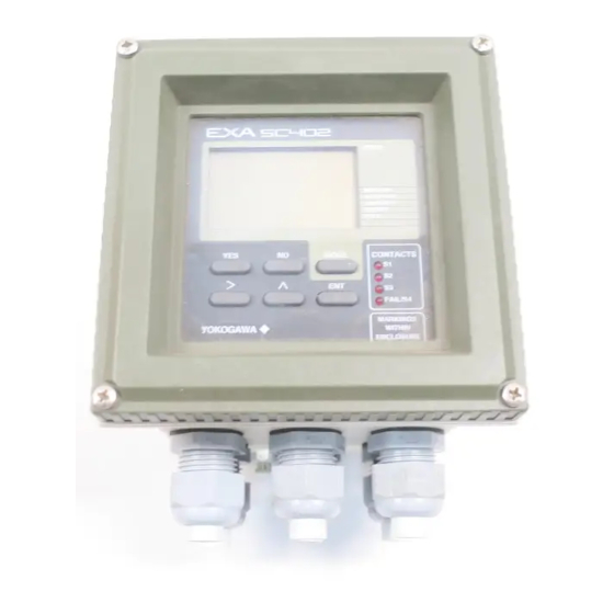
: Adjust digit : Confirm change Broken line indicates area that can be seen through front cover Figure 4-1. SC402G operator interface 4-2. Explanation of operating keys MODE key This key toggles between the measuring and maintenance modes. Press once to obtain access to the maintenance function menu. -
Page 28: Setting Passcodes
4. Operation; Display Function and Setting 4-3. Setting passcodes 4-3-1. Passcode protection In Service Code 52, EXA users can set passcode protection for each one of the three operating levels, or for any one or two of the three levels. This procedure should be completed after the initial commissioning (setup) of the instrument. -
Page 29: Display Functions
SETPOINTS SETPOINTS CALIBRATE RANGE Current DISPLAY SET HOLD TEMP. HOLD output 1 SERVICE S / c m CONTACTS MODE FAIL/S4 Current output 2 YOKOGAWA Press YES to fix S / c m the selected second line of display IM 12D08N04-01E... -
Page 30: Parameter Setting
5. Parameter Setting Parameter setting Before using the SC402G Conductivity Converter, you need to set its parameters to match the measurement range and operating conditions, and to enable required func- tions. This section describes the setting requirements. IM 12D08N04-01E... -
Page 31: Maintenance Mode
5. Parameter Setting 5-1. Maintenance mode 5-1-1. Introduction Standard operation of the EXA instrument involves use of the Maintenance (or operat- ing) mode to set up some of the parameters. Access to the maintenance mode is available via the six keys that can be pressed through the flexible window in the instrument front cover. -
Page 32: Manual Activation Of Hold
SETPOINTS RANGE SET HOLD TEMP. SERVICE CONTACTS MODE FAIL/S4 YOKOGAWA MODE HOLD CALIBRATE HOLD MEASURE Note: The HOLD feature must first be activated in the commissioning mode section 5.2.4 Note: Even though HOLD is activated, if Auto Return is enabled (factory default setting) and no keystroke is made for 10 min, HOLD will be released. -
Page 33: Setpoint Adjustment
MEASURE SETPOINTS RANGE SET HOLD TEMP. SERVICE CONTACTS MODE FAIL/S4 YOKOGAWA MODE For adjustments, m S / c m m S / c m follow procedures as in section 5.2.2 m S / c m Setpoint 3 and 4 when enabled in... -
Page 34: Commissioning Mode
2. Choose from Table, temperature or PI control. Hold The EXA SC402G converter has the ability to “HOLD” the output during maintenance periods. This parameter should be set up to hold the last measured value, or a fixed value to suit the process. -
Page 35: Setpoints
5. Parameter Setting 5-2-2. Setpoints MODE S / c m MEASURE SETPOINTS SETPOINTS CALIBRATE RANGE DISPLAY SET HOLD HOLD TEMP. SERVICE S / c m S / c m repeated keystrokes S / c m S / c m S / c m S / c m S / c m S / c m... - Page 36 5. Parameter Setting Process Alarms on Analogue control setpoint S.3 and S.4 are is only available when only available when enabled in Service Code 31 enabled in Service Codes 40-49 S / c m Adjust setpoint value Setpoint confirmed. using > ENT keys Return to mode as shown for setpoint 1.
-
Page 37: Range
5. Parameter Setting 5-2-3. Range MODE S / c m S / c m MEASURE SETPOINTS SETPOINTS CALIBRATE RANGE DISPLAY SET HOLD TEMP. HOLD SERVICE S / c m See facing page S / c m S / c m S / c m S / c m m S / c m... - Page 38 5. Parameter Setting Choose Range to adjust, then set begin scale (0%) and end scale (100%) of the mA output signal, using the >, ,and ENT keys. Selection of mA output (0-20 / 4-20 mA) is in Service Code 30. The decimal point and unit setting can be changed as described before in Setpoint Settings.
-
Page 39: Hold
5. Parameter Setting 5-2-4. Hold MODE S / c m MEASURE SETPOINTS SETPOINTS CALIBRATE RANGE SET HOLD DISPLAY HOLD TEMP. SERVICE HOLD deactivated, return to commissioning menu. HOLD HOLD HOLD active last measured value. Note: Even though HOLD is activated, if Auto Return is enabled (factory default setting) and no keystroke is made for 10 min, HOLD will be released. - Page 40 5. Parameter Setting HOLD value set, return to commissioning menu. HOLD HOLD HOLD HOLD Set HOLD "fixed value" HOLD for mA2. HOLD Set HOLD "fixed value" for mA1. 5-11 IM 12D08N04-01E...
-
Page 41: Temperature Compensation
5. Parameter Setting 5-2-5. Temperature compensation 1. Why temperature compensation? The conductivity of a solution is very dependent on temperature. Typically for every 1 °C change in temperature the solution conductivity will change by approximately 2 %. The effect of temperature varies from one solution to another and is determined by several factors like solution composition, concentration and temperature range. - Page 42 5. Parameter Setting 6. Adjust the display indication to the noted value at the reference temperature 7. Check that the temperature compensation factor has been changed 8. Insert the conductivity cell into the process again. 4. Other possibilities (section 5-3-3) 1.
-
Page 43: Service
5. Parameter Setting 5-2-6. Service MODE S / c m MEASURE SETPOINTS SETPOINTS CALIBRATE RANGE DISPLAY SET HOLD HOLD TEMP. SERVICE After changing the parameter, the instrument first goes into reset to load the parameter specific default values. / c m Example: Service Code 01 Select main parameter for SC... -
Page 44: Notes For Guidance In The Use Of Service Coded Settings
5. Parameter Setting 5-3. Notes for guidance in the use of service coded settings Note: Do not enter (or select) any service codes not described in this manual. Should you accidentally enter such a code, press the MODE key to exit Setting mode to Measure- ment mode. -
Page 45: Parameter Specific Functions
Code 5 *POL.CK The EXA SC402G has a polarisation check capable of monitoring the signal from the cell for distortion of capacitive or polarisation errors. If there is a problem with the installation or the cell becomes fouled, this will trigger E1. - Page 46 5. Parameter Setting Code Display Function Function detail Y Z Default values Parameter spewcific functions *SC.RES Select main parameter Conductivity Cond. Resistivity *4-ELEC Select 2/4-EL system 2-Electrode measurement system 2-El. 4-Electrode measurement system *0.10xC Set celconstant Press NO to step through choice of 0.100 cm-1 multiplying factors on the second display.
-
Page 47: Temperature Measuring Functions
5. Parameter Setting 5-3-2. Temperature measuring functions Code 10 *T.SENS Selection of the temperature compensation sensor. The default selection is the PT1000 sensor, which gives excellent precision with the two wire connections used. The other options give the flexibility to use a very wide range of other conductivity/resistivity sensors. - Page 48 5. Parameter Setting Code Display Function Function detail Y Z Default values Temperature measuring functions *T.SENS Temperature sensor Pt1000 Pt1000 Ni100 PB36NTC Pt100 8k55 (8.55k‰NTC) *T.UNIT Display in ßC or ßF ßC ßC ßF *T.ADJ Calibration temperature Adjust reading to allow for cable None resistance.
-
Page 49: Temperature Compensation Functions
5. Parameter Setting 5-3-3. Temperature compensation functions Code 20 *T.R.°C Choose a temperature to which the measured conductivity (or resistivity) value must be compensated to. Normally 25°C is used, therefore this temperature is chosen as default value. Limitations for this setting are: 0 to 100 °C. If T.UNIT in code 11 is set to °F, default value is 77°F and the limitations are 32 - 212°F. - Page 50 5. Parameter Setting Code Display Function Function detail Y Z Default values Temperature compensation functions *T.R.˚C Set reference temp. Use >, , ENT keys to set value 25˚C *T.C.1 Set temp. coef. 1 Adjust compensation factor for mA1 2.1%/˚C output, if set to TC in section 5-2-5. Set value with >, , ENT keys *T.C.2 Set temp.
-
Page 51: Ma Output Functions
5. Parameter Setting 5-3-4. mA output functions Code 30 Select 4-20mA or 0-20mA according to associated equipment (recorders, con- trollers etc.) Code 31 *OUTP.F Note: For resistivity measurement, read resistivity in stead of conductivity. Output mA1 (terminals 61&62) Conductivity linear Conductivity with 21 point output table. - Page 52 5. Parameter Setting Code Display Function Function detail Z Default values mA output functions mA output range mA1 = 0-20 mA mA1 = 4-20 mA 4-20mA mA2 = 0-20 mA mA2 = 4-20 mA 4-20mA *OUTP.F mA output functions SC on mA 1 Cond.
-
Page 53: Contact Outputs
5. Parameter Setting 5-3-5. Contact outputs Code 40 *S1, *S2 Process relays can be set for a variety of alarm and control function. 41, 42 *S3 & *S4 and 43 Digit "X" sets the type of trigger: Off means that the relay is not active Low setpoint means that the relay is triggered by a decreasing measurement. - Page 54 5. Parameter Setting Code Display Function Default values Function detail Contents Relay 1 settings 2.0.0 Low setpoint High High setpoint Note: Main process "HOLD" active means cond. or resist. Alarm Process alarm whichever is set in Proportional duty cycle control code #1 Proportional frequency control Temperature alarm...
- Page 55 5. Parameter Setting Cond./Resist. Setpoint Hys. LED off LED on LED off Delay time Delay time t (sec) Fig. 5-3. Delay time and Hysteresis % duty cycle control Pulse period Time Proportional range Setpoint % of output range Fig. 5-4. Duty cycle control 5-26 IM 12D08N04-01E...
- Page 56 5. Parameter Setting % controller output Maximum pulse frequency 0.3 s 50 % pulse frequency Potential Time No pulses range Setpoint % of output range Fig. 5-5. Pulse frequency control 5-27 IM 12D08N04-01E...
-
Page 57: User Interface
5. Parameter Setting 5-3-6. User interface Code 50 *RET. When Auto Return is enabled, the converter reverts to measuring mode from anywhere in the configuration menus, when no keystroke is made for 10 min even though HOLD is activated with HOLD function enabled. Code 51 *MODE The adjustment of the contact setpoints can be setup for operation in the... - Page 58 5. Parameter Setting Code Display Function Function detail Default values User interface *RET Auto return Auto return to measuring mode Off Auto return to measuring mode On *MODE Mode setup Setpoints in maintenance mode Off Setpoints in maintenance mode On *PASS Passcode Maintenance passcode Off...
-
Page 59: Setting Time
5. Parameter Setting 5-3-7. Setting Time Code 61 *HOUR Allows you to set current time. *MINUT *SECND *YEAR *MONTH *DAY Code Display Function Function detail X Y Z Default values Communication *HOUR Clock setup Adjust to current date and time using *MINUT >, , ENT keys... -
Page 60: Calibration
6-1 When is calibration necessary? Calibration of conductivity/resistivity instruments is normally not required, since Yokogawa delivers a wide range of sensors, which are factory calibrated traceable to NIST standards. The cell constant values are normally indicated on the top of the sensor or on the integral cable. -
Page 61: Calibration Procedure
SETPOINTS appears, press NO first. CALIBRATE DISPLAY HOLD CONTACTS MODE FAIL/S4 YOKOGAWA MODE S / c m S / c m S / c m Put the sensor in standard S / c m solution. Press YES. Set the value S / c m using the >, , ENT key. -
Page 62: Calibration With Hold Active
If the SETP legend MEASURE SETPOINTS appears, press NO first. CALIBRATE DISPLAY HOLD CONTACTS MODE FAIL/S4 YOKOGAWA MODE HOLD S / c m HOLD S / c m HOLD S / c m HOLD Put the sensor in standard S / c m solution. - Page 63 6. Calibration IM 12D08N04-01E...
-
Page 64: Maintenance
7. Maintenance Maintenance 7-1. Periodic maintenance for the EXA 402 converter The EXA transmitter requires very little periodic maintenance. The housing is sealed to IP65 (NEMA 4X) standards, and remains closed in normal operation. Users are required only to make sure the front window is kept clean in order to permit a clear view of the display and allow proper operation of the pushbuttons. -
Page 65: Periodic Maintenance Of The Sensor
7. Maintenance 7-2. Periodic maintenance of the sensor NOTE Maintenance advice listed here is intentionally general in nature. Sensor maintenance is highly application specific. In general conductivity/resistivity measurements do not need much periodic mainte- nance. If the EXA indicates an error in the measurement or in the calibration, some action may be needed (ref. -
Page 66: Troubleshooting
Incorrect programming by the user can be corrected according to the limits set in the following text. In addition, the EXA SC402G also checks the sensor to establish whether it is still functioning within specified limits. - Page 67 Air set impossible Too high zero due to cable capacitance Replace cable EEPROM write failure Fault in electronics Try again, if unsuccessful contact Yokogawa USP limit exceeded Poor water quality Check process Cable resistance influence to temperature Cable resistance too high Check cable exceeds +/- 15°C...
-
Page 68: Spare Parts
9. Spare Parts Spare Parts The appendix which follows contains the Customer Maintenance Parts List (CMPL). IM 12D08N04-01E... - Page 69 9. Spare Parts IM 12D08N04-01E...
-
Page 70: Appendix
10. Appendix 10. Appendix 10-1. User setting for non-linear output table (code 31, 35 and 36) Output signal value Output 0-20 4-20 25.6 10.4 11.2 12.8 13.6 14.4 15.2 16.8 17.6 17.6 18.4 19.2 20.0 10-2. User entered matrix data (code 22 to 28) Medium: T1 data T2 data T3 data T4 data T5 data Code 23 Temperature T1...T5... -
Page 71: Matrix Data Table (User Selectable In Code 22)
10. Appendix 10-3. Matrix data table (user selectable in code 22) Matrix, Solution Temp (°C) Data 1 Data 2 Data 3 Data 4 Data 5 HCl-p (cation) 0 ppb 4 ppb 10 ppb 20 ppb 100 ppb 0.0116 µS/cm 0.0228 µS/cm 0.0472 µS/cm 0.0911 µS/cm 0.450 µS/cm... -
Page 72: Sensor Selection
0.008/cm to 50.0/cm. 10-4-3. Selecting a temperature sensor The EXA SC402G reaches its highest accuracy when used with a Pt1000 temperature sensor. This may influence the choice of the conductivity/resistivity sensor, as in most cases the temperature sensor is integrated in the conductivity/resistivity sensor. -
Page 73: Usp Item 645 Water Purity Monitoring
1 to avoid them having to carry out the complicated laboratory checks in Stages 2 and 3. How have we accomplished this in SC402G? 1. In Software Rev. 1.2, (and later versions) we have defined an Error Code: E13. This is independent of what range the customer is measuring or what temperature compensation method he is using for water quality monitoring. - Page 74 10. Appendix Setting up SC402G for USP item 645 monitoring First enable USP item 645 in service code 57. Change the setting from 0 (default) to 1 (enabled). This activates uncompensated conductivity in the display menu. The E13 alarm feature is also enabled.
-
Page 75: User Setting Table
10. Appendix 10-7. User setting table FUNCTION SETTING DEFAULTS USER SETTINGS Parameter specific functions *SC.RES 0 *4-Elec 2-Elec. *0.10xC 0.10xC Factor 1.000 *AIR Perform zero calibration *POL.CK 0 Temperature measuring functions *T.SENS 0 Pt1000 °C *T.UNIT *T.ADJ None *T.COMP 0 *T.COEF 0.0 %/°C Temperature compensation functions... - Page 76 10. Appendix FUNCTION SETTING DEFAULTS USER SETTINGS User Interface *RET *MODE *PASS 0.0.0 all off *Err.01 hard fail *Err.05 hard fail *Err.06 hare fail *Err.07 hard fail *Err.08 hard fail *Err.13 Soft fail *Err.22 soft fail *SOFT LCD + Fail *E5.LIM kΩ...
-
Page 77: Configuration Checklist For Sc402G
10. Appendix 10-8. Configuration checklist for SC402G Standard Configuration Options Reference for change Measured Variable(s) primary inputs Conductivity (SC) and Temp Resistivity i.s.o Conductivity code 01 0.000 µS/cm - 1.000 mS/cm any span within 0.000µS/cm - 1999mS/cm "range" conductivity range Auto ranging µS/cm - mS/cm Choice out of fixed µS/cm or mS/cm... - Page 78 For G1/2 screw when /AFTG specified K9316AF For 1/2NPT screw Do not exchange these parts. Call serviceman. CMPL 12D08N04-01E All Rights Reserved, Copyright © 1996, Yokogawa Electric Corporation. Subject to change without notice. 1st Edition : Jan. 2004 (YK) Yokogawa Electric Corporation...
- Page 79 Pipe/Wall Mounting Hardware Panel Mounting Hardware (Option Code : /U) (Option Code : /PM) Sun Protection Cover (Option Code: /H3, /H4) Item Part No. Description K9171SS Mounting Set (/U) Y9608KU Screw D0117XL-A U-Bolt Assembly K9171SY Plate K9171SX Bracket K9171ST Mounting Set (/PM) Y9520LU Screw K9171SW...
- Page 80 For G1/2 screw when /AFTG specified K9316AF For 1/2NPT screw Do not exchange these parts. Call serviceman. CMPL 12D08N04-02E All Rights Reserved, Copyright © 1996, Yokogawa Electric Corporation. Subject to change without notice. 1st Edition : Jan. 2004 (YK) Yokogawa Electric Corporation...
- Page 81 Pipe/Wall Mounting Hardware Panel Mounting Hardware (Option Code : /U) (Option Code : /PM) Sun Protection Cover (Option Code: /H3, /H4) Item Part No. Description K9171SS Mounting Set (/U) Y9608KU Screw D0117XL-A U-Bolt Assembly K9171SY Plate K9171SX Bracket K9171ST Mounting Set (/PM) Y9520LU Screw K9171SW...
- Page 82 Revision Record Manual Title : Model SC402G Conductivity and Resistivity Converter [Style : S2] Manual Number : IM 12D08N04-01E Edition Date Remark (s) Oct. 2000 Newly published Feb. 2004 Style changed to S2. Sep. 2005 Revised pages are shown below.
- Page 83 Converter [Style : S2] Thank you for selecting Model SC402G "Conductivity and Resistivity Converter" The User's Manual M 12D08N04-01E 3rd Ed. supplied with this product has been revised as follows. Model name of SC4A has been changed to SC4AJ. Please make a note in your copy.
- Page 84 3-6. Sensor wiring Refer to figure 3-9, which includes drawings that outline sensor wiring. The EXA SC402G can be used with a wide range of commercially available sensor types if provided with shielded cables, both from Yokogawa and other manufacturers.
- Page 85 Code 5 *POL.CK The EXA SC402G has a polarisation check capable of monitoring the signal from the cell for distortion of capacitive or polarisation errors. If there is a problem with the installation or the cell becomes fouled, this will trigger E1.
- Page 86 5. Parameter Setting 5-3-2. Temperature measuring functions Code 10 *T.SENS Selection of the temperature compensation sensor. The default selection is the PT1000 sensor, which gives excellent precision with the two wire connections used. The other options give the flexibility to use a very wide range of other conductivity/resistivity sensors.
- Page 87 5. Parameter Setting 5-3-6. User interface Code 50 *RET. When Auto Return is enabled, the converter reverts to measuring mode from anywhere in the configuration menus, when no keystroke is made for 10 min even though HOLD is activated with HOLD function enabled. Code 51 *MODE The adjustment of the contact setpoints can be setup for operation in the...
- Page 88 10. Appendix 10-8. Configuration checklist for SC402G Standard Configuration Options Reference for change Measured Variable(s) primary inputs Conductivity (SC) and Temp Resistivity i.s.o Conductivity code 01 conductivity range 0.000 S/cm - 1.000 mS/cm any span within 0.000 S/cm - 1999mS/cm "range"...
Need help?
Do you have a question about the SC402G and is the answer not in the manual?
Questions and answers