
Related Manuals for YOKOGAWA EXA DO402G


Summary of Contents for YOKOGAWA EXA DO402G
- Page 1 User’s Model DO402G [Style: S3] Manual Dissolved Oxygen Converter IM 12J05D02-01E IM 12J05D02-01E 7th Edition...
-
Page 2: Table Of Contents
4-3. Setting passcodes ..................4-3 4-4. Display functions (default) ................4-4 5. Parameter setting ....................5-1 5-1. Maintenance mode ..................5-1 5-1-1. Manual activation of Hold ....................5-2 IM 12J05D02-01E 7th Edition: Feb. 2012(YK) All Rights Reserved, Copyright © 2003, Yokogawa Electric Corporation IM 12J05D02-01E... - Page 3 7-1. Overall dissolvedoxygen metering system ............. 7-1 7-1-1. Inspection and maintenance to be implemented periodically ..........7-1 7-1-2. Inspection and maintenance to be implemented on occasion ........7-1 7-2. Periodic maintenance for the EXA DO402G converter ........7-2 7-3. Fuse Replacement ..................7-2 8. Troubleshooting ....................8-1 8-1.
- Page 4 11. Appendix 2 QUALITY INSPECTION ..............11-1 Customer Maintenance Parts List (for Style: S3) ....CMPL 12J05D02-03E Revision Record ......................i IM 12J05D02-01E...
-
Page 6: Preface
• If the product is not used in a manner specified in this manual, the safety of this product may be impaired. Yokogawa is not responsible for damage to the instrument, poor performance of the instrument or losses resulting from such, if the problems are caused by: •... - Page 7 In the event of warranty claim, the defective goods should be sent (freight paid) to the service depart- ment of the relevant sales organization for repair or replacement (at Yokogawa discretion). The following information must be included in the letter accompanying the returned goods: •...
-
Page 8: Introduction And General Description
This manual also includes a basic troubleshooting guide to answer typi- cal user questions. Yokogawa can not be responsible for the performance of the EXA analyzer if these instructions are not followed. 1-1. Instrument Check Upon delivery, unpack the instrument carefully and inspect it to ensure that it was not damaged during shipment. -
Page 9: Application
Because the EXA is suitable for use as a monitor, a controller or an alarm instrument, program configuration possibilities are numerous. Details provided in this user’s manual are sufficient to operate the EXA with all Yokogawa sensor systems and a wide range of third-party commercially available probes. For best results, read this man- ual in conjunction with the corresponding sensor user’s manual. -
Page 10: General Information
Introduction 1-3 1-3. General information Flexibility, reliability and low maintenance are among the benefits provided by the EXA DO402G dis- solved oxygen analyzer. Designed to meet the exacting requirements of measuring dissolved oxygen in the modern industrial environment, it contains many features to ensure the best precision whatever the application. - Page 11 1-4 Introduction Display functions and ranges The display continuously gives you all necessary information at a glance. The process values are shown in easily readable programmable units. Either mg/l. % saturation or ppm can be chosen. The user-interface is simplified to a basic set of 6 keys accessible through the flexible window cover. It uses a simple step by step, question and answer style to communicate with the operator by giving mes- sages on the second line of the display and indicating which keys are to be pressed in the display.
-
Page 12: Configuration Checklist For Do402
Introduction 1-5 Logbook Software record of important events and diagnostic data. Available through RS485, for use with the Yokogawa PC402 communication software. Serial Communication Bi-directional according to the EIA-485 standard using HART-protocol and PC402 software. 1-4. Configuration checklist for DO402... -
Page 13: System Configuration
1-6 Introduction 1-5. System Configuration Dissolved Oxygen Converter Holders, Holders with Cleaning System Dissolved Oxygen Sensor Floating Ball Holder DO402G Output Signal : Guide Pipe DO70G 4 to 20 m A DC or PH8HG PB350G PB360G 0 to 20 m A DC Alarm Contact Output 4-Contact Point,... -
Page 14: The Holders
1-5-2. The holders a. PB30 floating ball holder All Yokogawa sensors are compatible with the floating ball holder that is specified in GS12J6K4 and GS12J5A1. b. FD30 immersion fitting The DO30 sensor is compatible with the FD30 immersion holder as specified in GS12J6K4 and with all flow fittings and flow fitting subassemblies that are specified in GS12D7K2. -
Page 16: Do402G Specifications
: The DO402G Dissolved Oxygen : 0- 50 ºC converter measures the cur- Sensor types: Pt100 or Pt1000 rent, that is generated by the RTD; PB36 (Yokogawa compat Dissolved Oxygen sensor. The ible); flexibility of the input circuit 22 k NTC (Ingold compatible) -
Page 17: Operating Specifications
2-2 Specification J. Contact outputs Power consumption - General : Four (4) SPDT relay contacts : Maximum 10 VA for steady with LED indicators. For S1, operation M. Safety and EMC conforming standards S2, and S3, the LED is on when relay is powered. -
Page 18: Model And Suffix Codes
Specification 2-3 Note on performance specifications: The distance between the ensor and trans The specifications are expressed with sim- mitter can be up to 50 m if the WTB10 junc ulated inputs, because the DO402G can tion box is used. This junction box can be used with many different sensors with not be used for the DO70G, for which the their unique characteristics. -
Page 20: Installation And Wiring
Installation and wiring 3-1 3. INSTALLATION AND WIRING 3-1. Installation and dimensions 3-1-1. Installation site WARNING WARNING This instrument is a Class A product, and it is designed for use in the industrial environment. Please use this instrument in the industrial environment only. The EXA converter is weatherproof and can be installed inside or outside. - Page 21 3-2 Installation and wiring Unit: mm (inch) (0.91) M6, 4 screws 12 max.(panel thickness) Panel cutout dimensions (0.47) M5, 2 screws (3.94) (5.43) (5.43) (7.01) Figure 3-2 . Panel mounting diagram (Option Code: /PM) Example of bracket used for pipe mounting M6, 4 screws (7.40) (6.85)
-
Page 22: Wiring
Installation and wiring 3-3 3-2. Wiring 3-2-1. Wiring of DO30G DO402G Output signal (4 to 20mA DC or 0 to 20mA DC) Power supply mA 1 Output signal mA 2 Contact (4 to 20mA DC or 0 to 20mA DC) output S1 SCREEN High and low... -
Page 23: Preparation
3-4 Installation and wiring DANGER • Never apply power to the DO402G converter and other instruments connected to the DO402G converter until all wiring is completed. WARNING • This product complies with the CE marking and CSA certified. Where compliance with the CE marking and relevant standard is necessary, the following wiring is required. -
Page 24: Wiring The Power Supply
Installation and wiring 3-5 FRONT GLANDS REAR GLANDS Power Sensor Output Contact signals output Contact RS485 output S4/FAIL Contact intput Figure 3-6. System configuration 3-3. Wiring the power supply 3-3-1. General precautions Make sure the power supply is switched off. Also, make sure that the power supply is correct for the specifications of the EXA and that the supply agrees with the voltage specified on the textplate. -
Page 25: Access To Terminal And Cable Entry
3-6 Installation and wiring 3-3-2. Access to terminal and cable entry Terminals 1 and 2 on the bottom terminal strip are used for the power supply. Guide the power cables through the gland closest to the power supply terminals. The terminals will accept wires of 2.5 mm AWG). -
Page 26: Ac Power
If errors are displayed or a valid meas- ured value is not shown, consult the troubleshooting section (Chapter 8) before calling Yokogawa. (M4 screw) Figure 3-9. Grounding the housing... -
Page 27: Wiring The Contact Signals
3-8 Installation and wiring 3-4. Wiring the contact signals 3-4-1. General precautions The contact output signals consist of voltage-free relay contacts for switching electrical appliances (SPDT). They can also be used as digital outputs to signal processing equipment (such as a controller or PLC). -
Page 28: Wiring The Analog Output Signals
Installation and wiring 3-9 3-5. Wiring the analog output signals 3-5-1. General precautions The analog output signals of the EXA transmit low power standard industry signals to peripherals like control systems or strip-chart recorders (Figure 3-6). 3-5-2. Analog output signals The output signals consist of active current signals of either 0-20 mA or 4-20 mA. -
Page 29: Wiring Other Galvanic Sensors
3-10 Installation and wiring 3-7. Wiring other galvanic sensors Consult the users manual for the color identification of the sensor cable and connect temperature com- pensator, cathode and anode to the terminals: 11, 12, 13 and 15 as described above. Connect the cable shield to 14 if there is one available. -
Page 30: Wiring Polarographic Sensors
Installation and wiring 3-11 3-9. Wiring polarographic sensors Consult the owners manual for the color identification of the sensor cable and connect temperature com- pensator, cathode and anode to terminals 11, 12, 17 and 18 in this sequence. Connect the cable shield (when provided) to terminal 14. Note: A shorting cable is connected between converter terminals 13 and 17. -
Page 32: Operation; Display Functions And Setting
Operation 4-1 4. OPERATION; DISPLAY FUNCTIONS AND SETTING 4-1. Operator interface This section provides an overview of the operation of the EXA operator interface. The basic procedures for obtaining access to the three levels of operation are described briefly. For a step-by-step guide to data entry, refer to the relevant section of this instruction manual. -
Page 33: Explanation Of Operating Keys
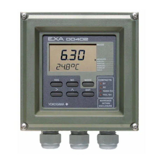
MODE mode access key Selection keys WASH/S3 YES : Accept setting Relay contact FAIL/S4 : Change setting status indicators MARKINGS YOKOGAWA WITHIN ENCLOSURE Adjustment keys > : Choose digit to Measure/Maintenance adjust mode key : Adjust digit Broken line indicates area... -
Page 34: Setting Passcodes
Operation 4-3 4-3. Setting passcodes In Service Code 52, EXA users can set passcode protection for each one of the three operating levels, or for any one or two of the three levels. This procedure should be completed after the initial commis- sioning (setup) of the instrument. -
Page 35: Display Functions (Default)
4-4 Operation 4-4. Display functions (default) Display Access MEASURE AIR.CAL H2O.CAL DISPLAY MAN.CAL Cell current DISPLAY HOLD MODE (See Air AIR.CAL calibration DISPLAY Slope Chapter 6) (See H Zero calibration, calibration when enabled Chapter 6) in service code 51 H2O.CAL DISPLAY (See Manual calibration... -
Page 36: Parameter Setting
Parameter setting 5-1 5. PARAMETER SETTING 5-1. Maintenance mode Standard operation of the EXA instrument involves use of the maintenance (or operating) mode to set up some of the parameters. Access to the Maintenance mode is available via the six keys that can be pressed through the flexible window in the instrument cover. -
Page 37: Manual Activation Of Hold
RANGE SET HOLD WASH SERVICE CONTACTS MODE WASH/S3 FAIL/S4 MARKINGS YOKOGAWA WITHIN ENCLOSURE MODE AIR.CAL HOLD MEASURE Note: The HOLD feature must first be activated in the commissioning mode section 5-2-3. Note: The HOLD feature must first be activated in the commissioning mode section 5.--... -
Page 38: Manual Wash Start/Stop
SETPOINTS RANGE SET HOLD WASH SERVICE CONTACTS MODE WASH/S3 FAIL/S4 MARKINGS YOKOGAWA WITHIN ENCLOSURE MODE MODE AIR.CAL WASH ACTIVE press YES to stop. Note: Note: Wash must first be switched on in commissioning mode section 5.5. Relay S3 must first be set for “WASH” in service code 42 and set for adjustment in the maintenance mode, by service code 5.1. -
Page 39: Setpoint Adjustment
Setpoints available will depend on their SET HOLD WASH configuration in the Service Code. SERVICE CONTACTS MODE WASH/S3 FAIL/S4 MARKINGS YOKOGAWA WITHIN ENCLOSURE MODE AIR.CAL For adjustments, follow procedures as in section 5-2-1. Setpoint 3 and 4 when enabled in... -
Page 40: Commissioning Mode
Parameter setting 5-5 5-2. Commissioning mode In order to obtain peak performance from the EXA converter, you must set it up for each custom applica- tion. Refer to section 1-4 for standard configurations and options. *SETP Alarms are set by default S1 - high process alarm S2 - low process alarm S3 - WASH... -
Page 41: Setpoints
5-6 Parameter setting 5-2-1. Setpoints MODE MEASURE AIR.CAL SETPOINTS H2O.CAL RANGE MAN.CAL SET HOLD DISPLAY WASH HOLD SERVICE repeated keystrokes IM 12J05D02-01E... - Page 42 Parameter setting 5-7 Process Alarms on S3 and S4 are only available when enabled in Service Codes 40-49 Analogue control setpoint is only available when enabled in Service Code 31 Adjust setpoint value using > ENT keys as shown for setpoint 1. Setpoint confirmed- return to commissioning menu.
-
Page 43: Range
5-8 Parameter setting 5-2-2. Range MODE MEASURE AIR.CAL SETPOINTS H2O.CAL RANGE MAN.CAL SET HOLD DISPLAY WASH HOLD SERVICE See facing page IM 12J05D02-01E... - Page 44 Parameter setting 5-9 Choose Range to adjust, then set begin scale (0%) and end scale (100%) of the mA output signal, using the >, ,and ENT keys. Selection of mA output(0-20 / 4-20 mA) is in Service Code 30. Range Selection Options Note: Range 2 does not appear are determined by Service...
-
Page 45: Hold
5-10 Parameter setting 5-2-3. Hold MODE MEASURE AIR.CAL SETPOINTS H2O.CAL RANGE MAN.CAL SET HOLD DISPLAY WASH HOLD SERVICE HOLD deactivated, return to commissioning menu. HOLD HOLD active last measured value. IM 12J05D02-01E... - Page 46 Parameter setting 5-11 HOLD values set,return to commissioning menu. HOLD HOLD HOLD HOLD Set HOLD "fixed value" HOLD for mA2. HOLD Set HOLD "fixed value" for mA1. IM 12J05D02-01E...
-
Page 47: Wash
5-12 Parameter setting 5-2-4. Wash MODE (NOTE: The menu item "WASH" will not appear unless selected in Service Code 42) MEASURE AIR.CAL SETPOINTS H2O.CAL RANGE MAN.CAL SET HOLD DISPLAY WASH HOLD SERVICE Wash system timings are set with the >, , and ENT keys in the setpoint menu IM 12J05D02-01E... -
Page 48: Service
Parameter setting 5-13 5-2-5. Service MODE Note: MEASURE For information on how to set cell AIR.CAL SETPOINTS RANGE H2O.CAL current, see description in Section MAN.CAL SET HOLD DISPLAY WASH HOLD SERVICE 1-5, A4 Example: Service Code 01 Select Sensor Type for galvanic sensor Nominal cell current at 100% Saturation. -
Page 49: Notes For Guidance In The Use Of Service Coded Settings
Select 9 for other polarographic sensor, with the nominal cell current to be user defined. Select 9 for the DO70G sensor and input the nominal cell current of 60 nA. General Note: Dissolved oxygen sensors fall into two categories – galvanic and polarographic. Yokogawa offer both types: Settings for Yokogawa Sensors DO30 DO30 SM31. - Page 50 Parameter setting 5-15 Code Display Function Function detail Default values Parameter Specific functions Galvanic *S. TYPE Sensor type Polarographic 3.75 μA for 50 micron type *I.CELL Sensor output Galvanic 7.50 μA for 25 micron type User defined 3.75 μA *I.CELL Sensor output 50 nA Polarographic...
-
Page 51: Temperature Functions
5-16 Parameter setting 5-3-2. Temperature functions Code 10 *T.SENS Select temperature sensor to suit the measuring probe. Refer to instructions with DO sensor for which temperature sensor is used. Code 11 *T.UNIT Select °C or °F for temperature display. Code 12 *T.ADJ Adjust offset in temperature measurement when the sensor is at a stable known value. - Page 52 Parameter setting 5-17 Code Display Function Function detail Default values Temperature Measuring Functions *T.SENS Temp. Comp. Pt100 RTD Pt1000 RTD (DO30) PB36 = 2k2 NTC 22k NTC (SM31) (DO70G) *T.UNIT Temp units Celsius Fahrenheit *T.ADJ Temp adjust Adjustment +/- 7.5 °C or +/- 13.5 °F *T.MAN Manual TC Automatic temperature comp...
-
Page 53: Ma Output Settings
5-18 Parameter setting 5-3-4. mA output settings Code 30 Select 0-20 mA or 4-20 mA for each of the mA outputs. Code 31 *OUTP.F Select the parameter to be transmitted on each of the mA outputs. *D/R Select the control action when PI selected on mA2. Direct action gives an increasing output with an increase in measured value. - Page 54 Parameter setting 5-19 Code Display Function Function detail Default values mA Output Functions mA output Output 1 is 0- 20 mA Output 1 is 4- 20 mA Output 2 is 0- 20 mA Output 2 is 4-20 mA *OUTP.F Output function Process value on mA1 Table on mA1 Process value on mA2...
-
Page 55: Contact Outputs
5-20 Parameter setting 5-3-5. Contact outputs Code 40, *S1 & *S2 Process relays can be set for a variety of alarm and control function. 41, 42 & 43 Digit “X” sets the type of trigger: Off means that the relay is not active Low setpoint means that the relay is triggered by a decreasing measurement. - Page 56 Parameter setting 5-21 Code Display Function Function detail Default values Contact Settings *S 1 Contact S1 Contact 1 inactive 2.0.0 Low alarm configuration High alarm configuration Active during HOLD Activation by process value Proportional duty cycle Proportional pulse frequency Activation by temperature PI control inactive PI control active * S 2...
- Page 57 5-22 Parameter setting Code 44 *D.TIME The delay time (or dead time) sets the minimum relay switching time. This function can be adjusted to give a good alarm function in a noisy process, preventing the relay from “chattering” or repeatedly switching when the signal is close to the setpoint.
- Page 58 Parameter setting 5-23 Code Display Function Function detail Default values Contacts Settings *D.TIME Dead Time Delay after setpoint passed 0- 2.0 s 0.2 s *P.HYST Hysteresis Process value hysteresis 0-50 mg/l or 0-300 % 0.1 mg/l *T.HYST Temp hyst Temperature hysteresis 0- 5 °C (0- 12 °F) 0.5 °C *RANGE...
- Page 59 5-24 Parameter setting Control and Alarm Functions Control output (mA) Pl control on the 2nd mA output. The 2nd mA output can be configured to give a P/I (proportional and integral) control output. The setpoint, proportional band and integral time are each fully programmable.
- Page 60 Parameter setting 5-25 % duty cycle control t off > 0.1 sec Duty cycle t on t off Duty cycle t on > 0.1 sec Duty cycle Proportional Setpoint Time Range % of output range Figure 1. Duty cycle control 0.3 s % controller output Maximum pulse frequency...
-
Page 61: User Interface
5-26 Parameter setting 5-3-6. User interface Code 50 *RET When Auto return is enabled, the converter reverts to the measuring mode from anywhere in the configuration menus, when no button is pressed during the set time interval of 10 minutes. Code 51 *MODE The adjustment of the contact setpoints, and the manual operation of the... - Page 62 Parameter setting 5-27 Code Display Function Function detail Default values User Interface *RET Auto return No return to meas. from HOLD Return to meas after 10 min *MODE add. to MAINT Setpoint adj. disabled 0.0.0 Setpoint adj. also in MAINT Wash start disabled Wash start in maintenance mode Manual pressure disabled...
-
Page 63: Communication Setup
The settings should be adjusted to suit the communicating device connected to the RS485 port. *SET. *ADDR. For the Yokogawa PC402 software package, the default settings match the software as shipped. Code 61 *HOUR The clock/calendar for the logbook is set for current date and time as reference. - Page 64 Parameter setting 5-29 Code Display Function Function detail Default values Communication *COMM. Communication Set communication Set communication Communication write enable write Communication write protect protect *SET. Baud rate & parity Baud rate 1200 2400 4800 9600 9600 Parity Even *ADDR. Network address Set address 00 to 15 *HOUR...
-
Page 66: Calibration Procedure
Calibration 6-1 6. CALIBRATION PROCEDURE Calibration of the dissolved oxygen analyzer is performed in the following situations: • When a new dissolved oxygen sensor is installed. • When the membrane is replaced and/or the electrolyte solution is replaced • When the measuring error after cleaning exceeds the acceptable deviation from reference method •... -
Page 67: Diagnostic Functions Performed During Calibration
6-2 Calibration 6-1-2. Diagnostic functions performed during calibration The calibration is a semi-automatic calibration, which means that the sensor output is used for calcula- tion of sensor parameters after the readings have stabilized. The criteria for stabilization are set in serv- ice code 20. -
Page 68: Procedure For Air Calibration
MAN.CAL DISPLAY HOLD CONTACTS MODE WASH/S3 FAIL/S4 from *2 to *1 YOKOGAWA The instruments waits for the reading to stabilize. (The display flashes) When reading Is stable, to *2 the CAL.END message appears. Note: To start calibration with a zero solution,... -
Page 69: Calibration Procedure Using Water Calibration Method
6-4 Calibration 6-3. Calibration procedure using water calibration method 6-3-1. Preparation Move the sensor to a maintenance site and wash off any dirt on the membrane. Lightly wipe off any remaining water from the membrane with a soft tissue. Prepare the necessary equipment and reagents to be used for the span and (if required) zero calibration. Equipment for span calibration includes: •... -
Page 70: Procedure For Water Calibration
HOLD pressure is enabled. Press proceed. CONTACTS MODE WASH/S3 FAIL/S4 Place sensor in calibration YOKOGAWA solution from *2 to *2 to *1 The instruments waits for the reading to stabilize. (The display flashes) Note: To start calibration When reading Is stable, with a zero solution, the CAL.END message... -
Page 71: Calibration Method Using Manual Calibration Method
6-6 Calibration 6-4. Calibration method using manual calibration method 6-4-1. Preparation a. Cleaning Confirm that the readings of the analyzer are stable and measured with a clean sensor. Otherwise move the sensor to a maintenance site and wash off any dirt on the sensor membrane Move the sensor back to the process water and wait for the readings to stabilize. -
Page 72: Procedure For Manual Calibration
MAN.CAL DISPLAY HOLD CONTACTS MODE WASH/S3 FAIL/S4 YOKOGAWA If “X.X.1” is selected in Service Code 51, the M.PR.ON message will appear to indicate that manual pressure is enabled. Press YES to proceed. After briefly displaying WAIT, the display returns to the normal readout. - Page 73 6-8 Calibration Table 6-1. Solubility of oxygen (mg/l) in water as a function of temperature & salinity Temp Solubility of oxygen in water in equilibrium Correction to be substracted for each degree of salinity with air expressed in grams per kilogram of total salts in water @101.325kPa[pO [∆pO °C...
-
Page 74: Maintenance
Maintenance 7-1 7. MAINTENANCE It is important for maintaining the measurement accuracy of the EXA DO series of wire dissolvedoxygen metering system to perform inspection and maintenance at fixed intervals. It also serves to prevent prob- lems from arising. This chapter describes daily inspection and maintenance for the purpose of maintaining system perform- ance. -
Page 75: Periodic Maintenance For The Exa Do402G Converter
7-2 maintenance 7-2. Periodic maintenance for the EXA DO402G converter The DO402G converter requires very little periodic maintenance. The housing is sealed to IP65 (NEMA 4X) standards, and remains closed in normal operation. Users are required only to make sure the front window is kept clean in order to permit a clear view of the display and allow proper operation of the pushbuttons. - Page 76 Maintenance 7-3 How to replace the fuse 1) Before replacing the fuse, turn off power to the instrument at the external breaker. 2) Remove the instrument cover and the high-voltage shield plate. 3) Remove the cover from the fuse holder by pulling out by hand. 4) Remove the fuse and install a new, recommended or equivalent fuse on the holder.
-
Page 78: Troubleshooting
If the operation keys do not operate smoothly or the display fails (e.g., a missing character segment), repair of the printed circuit board (digital board) (replacement with a new one) is required. After the printed circuit board is replaced, operation checks and parameter settings are necessary. Contact Yokogawa and request board-replacement work. IM 12J05D02-01E... -
Page 79: Measures In The Case Of Failure (Error) Detection
8-2 Troubleshooting 8-2. Measures in the case of failure (Error) detection If a failure is detected through the self-diagnosis of the DO402G dissolvedoxygen converter, the FAIL contact is closed. The FAIL lamp on the operation panel lights up and an error number appears in the data display. - Page 80 Re-enter a value within the permissible A value not within the permissible range range. is entered. All modes Instrument initialization failure Repair is necessary. Contact Yokogawa to request repair. All modes EPROM comparison failure Repair if necessary. Contact Yokogawa to request repair.
-
Page 82: Spare Parts
Spare parts 9-1 9. SPARE PARTS See Customer Maintenance Parts List. IM 12J05D02-01E... -
Page 84: Appendix
Appendix 10-1 10. APPENDIX Adjustable limits and defaults for settings in Commissioning Level 10-1. Setpoint Variable Default Lower limit Upper limit *OX1 19.5 mg/l 0.0 mg/l 50.0 mg/l 0.0 ppm 50.0 ppm 0.0 %sat 300 %sat *OX2 1.0 mg/l 0.0 mg/l 50.0 mg/l 0.0 ppm 50.0 ppm... -
Page 85: User Setting Table
10-2 Appendix 10-5. User setting table FUNCTION SETTING DEFAULTS USER SETTINGS Parameter specific functions *S.TYPE Galvanic (7 µA) *I.CELL 3.75 µA *CHECK 0.1.0 Zero Off Slope On Membrane Off *SAL.TY Temperature measuring functions *T.SENS Pt1000 *T.UNIT °C *T.ADJ None *T.MAN Calibration parameter functions *∆T.SEC sec. - Page 86 Appendix 10-3 FUNCTION SETTING DEFAULTS USER SETTINGS User Interface *RET *MODE 0.0.0 all off *PASS 0.0.0 all off *Err.01 hard fail *Err.02 hard fail *Err.03 hard fail *Err.04 hard fail *Err.07 hard fail *Err.08 hard fail *Err.09 hard fail *Err.12 hard fail *Err.16 soft fail...
- Page 87 Check setup Polarographic: outside -100 to 500 nA EEPROM write failure Fault in electronics Try again, if unsuccessful contact Yokogawa Abnormal measured value. Wrong DO sensor or temperaure Check code 01, 02, 10, The dissolved oxygen value (%sat.) sensor programmed.
- Page 88 Appendix 2 11-1 11. APPENDIX 2 QUALITY INSPECTION Quality DO402G Inspection Dissolved Oxygen Converter Standards Scope This inspection standard applies to the DO402G Dissolved Oxygen Converter. Inspection Items 2.1 Insulation resistance test * 2.2 Dielectric strength test 2.3 Current output test 2.4 Contact operation test 2.5 Temperature indication check * 2.6 Input current indication check...
- Page 89 11-2 Appendix 2 f. Press the [ ] key seven times. The data display will show “87” with the second digit of 7 flashing. g. Press the [ENT] key. The message display will show “ PASS .” (2) Setting Password 070 Press the [>] key once.
- Page 90 Appendix 2 11-3 Table 3 Temperature (°C) Data Display (°C) Resistance ( ) 1019.5 5 ±0.3 1097.3 25 ±0.3 1174.7 45 ±0.3 Input Current Indication Check Following Section 3.5, press the [ENT] key until the message display shows “GALVA1.” Turn SW1 on. Change the current of the standard current generator and check the data display.
- Page 91 11-4 Appendix 2 Atmospheric Pressure Indication Check Following Section 3.6, press the [ENT] key until the message display shows “PRESS.” Check that the data display indication at this time is within the range from 900 (hPa) to 1100 (hPa). Press the [ENT] key. The message display will show “READY.” Continue to press the [ENT] key to return to normal measurement mode.
- Page 92 Appendix 2 11-5 IM 12J05D02-01E...
- Page 94 For G1/2 screw when /AFTG specified. K9316AF For 1/2NPT screw when /ANSI specified. * Do not exchange these parts. Call service personnel. CMPL 12J05D02-03E All Rights Reserved, Copyright © 2007, Yokogawa Electric Corporation. Subject to change without notice. 1st Edition : Mar. 2007 (YK)
- Page 95 Pipe/Wall Mounting Hardware Panel Mounting Hardware (Option Code : /U) (Option Code : /PM) Sun Protection Cover (Option Code: /H3, /H4) Item Part No. Description K9171SS Mounting Set (/U) Y9608KU Screw D0117XL-A U-Bolt Assembly K9171SY Plate K9171SX Bracket K9171ST Mounting Set (/PM) Y9520LU Screw K9171SW...
- Page 96 Revision Record Manual Title : Model DO402G Dissolved Oxygen Converter [Style: S3] Manual Number : IM 12J05D02-01E Edition Date Remark (s) Apr. 2003 Newly published Feb. 2004 Style changed to S2 Sep. 2006 On p.ii, After-sales Warranty modified.; On p.2-3, Operating specifications modified.;...
- Page 98 Model DO402G [Style: S3] User’s Dissolved Oxygen Converter Manual Supplement Thank you for selecting our Model DO402G [Style: S3] Dissolved Oxygen Converter. User's Manual, IM 12J05D02-01E, 7th Edition, supplied with the product, some revisions/additions have been made. Please replace the corresponding pages in your copy with the attached, revised pages. Revisions: - Page 7-1 Some revision of Table 7-2.
- Page 99 Maintenance 7-1 7. Maintenance It is important for maintaining the measurement accuracy of the EXA DO series of wire dissolvedoxygen metering system to perform inspection and maintenance at fixed intervals. It also serves to prevent prob- lems from arising. This chapter describes daily inspection and maintenance for the purpose of maintaining system perform- ance.
- Page 100 8-2 Troubleshooting 8-2. Measures in the case of failure (Error) detection If a failure is detected through the self-diagnosis of the DO402G dissolved oxygen converter, the FAIL contact is closed. The FAIL lamp on the operation panel lights up and an error number appears in the data display.
- Page 101 Re-enter a value within the permissible A value not within the permissible range range. is entered. All modes Instrument initialization failure Repair is necessary. Contact Yokogawa to request repair. All modes EPROM comparison failure Repair if necessary. Contact Yokogawa to request repair.
- Page 102 For 1/2NPT screw when /ANSI specified. * Do not exchange these parts. Call service personnel. CMPL 12J05D02-03E All Rights Reserved, Copyright © 2007, Yokogawa Electric Corporation. Subject to change without notice. 1st Edition : Mar. 2007 (YK) 2nd Edition : Sep. 2012 (YK)
- Page 103 Pipe/Wall Mounting Hardware Panel Mounting Hardware (Option Code : /U) (Option Code : /PM) Sun Protection Cover (Option Code: /H3, /H4) Item Part No. Description K9171SS Mounting Set (/U) Y9608KU Screw D0117XL-A U-Bolt Assembly K9171SY Plate K9171SX Bracket K9171ST Mounting Set (/PM) Y9520LU Screw K9171SW...
Need help?
Do you have a question about the EXA DO402G and is the answer not in the manual?
Questions and answers