Sign In
Upload
Download
Table of Contents
Contents
Add to my manuals
Delete from my manuals
Share
URL of this page:
HTML Link:
Bookmark this page
Add
Manual will be automatically added to "My Manuals"
Print this page
×
Bookmark added
×
Added to my manuals
Manuals
Brands
YOKOGAWA Manuals
Media Converter
SC450G
User manual
YOKOGAWA SC450G User Manual
Conductivity converter
Hide thumbs
Also See for SC450G
:
Technical information
(51 pages)
1
2
3
4
5
6
7
8
Table Of Contents
9
10
11
12
13
14
15
16
17
18
19
20
21
22
23
24
25
26
27
28
29
30
31
32
33
34
35
36
37
38
39
40
41
42
43
44
45
46
47
48
49
50
51
52
53
54
55
56
57
58
59
60
61
62
63
64
65
66
67
68
69
70
71
72
73
74
75
76
77
78
79
80
81
82
83
84
page
of
84
Go
/
84
Contents
Table of Contents
Troubleshooting
Bookmarks
Table of Contents
Table of Contents>
Preface
Table of Contents>
Warranty and Service
Safety Precautions
CE Marking Products
Table of Contents
1 Introduction and General Description
Instrument Check
Application
2 General Specifications
3 Installation and Wiring
Installation and Dimensions
Installation Site
Mounting Methods
Wiring
Preparation
Cables, Terminals, Glands and Conduit Adapter
Wiring the Power Supply
General Precautions
Access to Terminal and Cable Entry
AC Power
DC Power
Grounding the Housing
Switching on the Instrument
Wiring the Contact Signals
General Precautions
Contact Outputs
Contact Input
Wiring the Ma-Output Signals
General Precautions
Analog Output Signals
Wiring the Sensor System
Sensor Wiring
Other Sensor Systems
Sensor Cable Connections Using Junction Box (Ba10) And Extension Cable
Wf10
4 Operation
Main Display Functions
Trending Graphics
Zoom in on Details
Actual Ma1
Actual Ma2
S1/S2/S3/S4
Factory)
Adjusted)
Polarization
Sensor Ohms
Last Calibrated At
Calibration Due at
Projected Calibration at
Hart ID
Software Revision
HART Device Revision
Logbook
Information Function
Setup-Calibration & Commissioning
Secondary-Primary Value Display Switch
Navigation of the Menu Structure
5 Menu Structure Commissioning
Configure Sensor
Temperature Setting
Temperature Compensation
Calibration Settings
Concentration
Ma Output Setup
Contact Output Setup
Fail
Simulate
Water for Injection Monitoring (USP 645 and EU 0169)
Input Contacts
Error Configuration
Logbook Configuration
Advanced Setup
Display Setup
6 Calibration
Cell Constant Manual
Cell Constant Automatic
Air (Zero) Calibration
Sample Calibration
Temperature Coefficient Calibration
Temperature Calibration
Operation of Hold Function During Calibration
General Comments on SC Calibration
7 Maintenance
Periodic Maintenance
Periodic Maintenance of the Sensor
Cleaning Methods
LCD Adjustment
Contrast Adjustment
8 Troubleshooting
Calibration Check
Polarization Check
Predictive Maintenance
Prediction of Cleaning Needed
Poor Calibration Technique
Error Displays and Actions
Appendices
Appendix 1 Temperature Compensation
Appendix 2 TDS Readings
Appendix 3 Calibration Solutions for Conductivity
Appendix 4 Sensor Selection for the SC450G
Appendix 5 How To Enter The Cell Constant For The Sc21□G, Sc8Sg, And Sc4Aj
Appendix 6 HART HHT (275/375) Menu Structure
Appendix 7 Control Drawing For Fm Approval
Parts List
Revision Record
Advertisement
Quick Links
1
Setup-Calibration & Commissioning
2
Calibration Settings
3
Calibration Check
4
Error Displays and Actions
Download this manual
User's
Manual
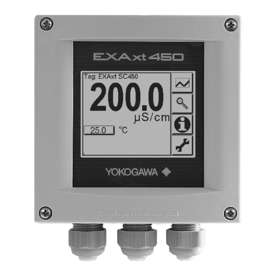
Model SC450G
Conductivity Converter
[Style: S2]
IM 12D08N05-01E
5th Edition
Table of
Contents
Previous
Page
Next
Page
1
2
3
4
5
Advertisement
Table of Contents
Need help?
Do you have a question about the SC450G and is the answer not in the manual?
Ask a question
Questions and answers
Related Manuals for YOKOGAWA SC450G
Media Converter YOKOGAWA PH450G Technical Information
Ph/orp/conductivity converters hart communication (51 pages)
Media Converter YOKOGAWA SC402G User Manual
Conductivity and resistivity converter (89 pages)
Media Converter YOKOGAWA Admag SE14 User Manual
Magnetic flow converter (107 pages)
Media Converter YOKOGAWA YEW 80 Series User Manual
Integrator (54 pages)
Media Converter YOKOGAWA SC150 Instruction Manual
(58 pages)
Media Converter Yokogawa Exaxt450 User Manual
Conductivity converter (84 pages)
Media Converter YOKOGAWA FLXA402 User Manual
4-wire converter, operation of converter (93 pages)
Media Converter YOKOGAWA ISC450G User Manual
Inductive conductivity converter (73 pages)
Media Converter YOKOGAWA PH450G User Manual
Ph and orp converter (91 pages)
Media Converter Yokogawa FLXA402 User Manual
4-wire converter opeartion of ph/orp (45 pages)
Media Converter YOKOGAWA FLXA402 User Manual
4-wire converter opeartion of isc (47 pages)
Media Converter YOKOGAWA FLXA402 Installation And Wiring
4-wire converter (43 pages)
Media Converter YOKOGAWA av550g User Manual
Zirconia oxygen analyzer averaging converter (213 pages)
Media Converter YOKOGAWA JUXTA PF1 User Manual
Pneumatic to electrical converter (4 pages)
Media Converter YOKOGAWA PH402G Instruction Manual
Ph (94 pages)
Media Converter YOKOGAWA FLXA402 Technical Information
4-wire converter, hart communication (37 pages)
This manual is also suitable for:
Exaxt450
Table of Contents
Print
Rename the bookmark
Delete bookmark?
Delete from my manuals?
Login
Sign In
OR
Sign in with Facebook
Sign in with Google
Upload manual
Upload from disk
Upload from URL


Need help?
Do you have a question about the SC450G and is the answer not in the manual?
Questions and answers