Table of Contents
Advertisement
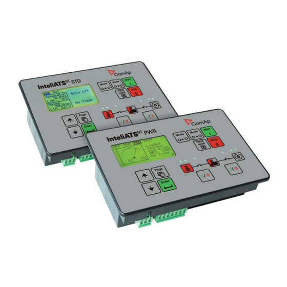
InteliATS
Automatic Transfer Switch Controller
IA-NT PWR unit
SW version 1.2, January 2010
January 2010
Copyright © 2010 ComAp s.r.o.
Written by Vlastimil Vostřák
Prague, Czech Republic
®
NT
ComAp, spol. s r.o.
Kundratka
2359/17, 180 00 Praha 8, Czech Republic
Tel: +420
246 012
111, Fax: +420 246 316 647
E-mail: info@comap.cz, www.comap.cz
Reference Guide
Advertisement
Table of Contents

Related Manuals for ComAp IA-NT PWR


Summarization of Contents
Document Information
Clarification of Notation
Explains the meaning of NOTE, CAUTION, and WARNING paragraphs.
Conformity Declaration
States the product's compliance with EC Low Voltage and EMC Directives.
General Guidelines
Manual Contents and Audience
Describes the manual's scope, purpose, and target users.
Software and Hardware Compatibility
Discusses compatibility between InteliATSNT software and hardware versions.
Controller Description
System Overview
Explains the function and features of the InteliATSNT controller.
Example Application Diagram
Illustrates a typical installation setup for the controller.
Configuration and Package Contents
Controller Configurability
Details how to adapt the controller's system to specific application needs.
Package Contents
Lists the accessories included with the InteliATSNT controller.
RS232 Communication Module Installation
Step-by-Step Installation
Provides a detailed procedure for installing the RS232 communication module.
Terminals and Front Panel
IA-NT PWR Terminals Layout
Shows the physical terminal connections on the IA-NT PWR unit.
Front Panel Controls and Display
Describes the user interface controls and display on the front panel.
Recommended Wiring Diagram
IA-NT PWR Wiring Schematic
Provides a visual guide for connecting the controller and associated components.
ATS Applications
AMF with Two Breakers and Feedbacks
Describes an Auto Mains Failure (AMF) application using MCB and GCB.
AMF with Two Breakers and Test on Load
AMF application with capability for test on load functionality.
AMF with Two-Position ATS
AMF application utilizing a two-position Automatic Transfer Switch.
AMF with Three-Position ATS
AMF application using a three-position Automatic Transfer Switch.
AMF with Manual Transfer and Neutral Control
AMF application with manual transfer and neutral position control.
AMF Without Battery Operation
Describes AMF operation when the controller is not supplied by a battery.
Getting Started
Installation Guidelines
General advice and best practices for installing the controller.
Power Supply Requirements
Details on voltage, current, and drop-out specifications for the power supply.
Power Supply and Output Protection
Power Supply Fusing
Recommended fusing for the controller's power supply connection.
Binary Output Protection
Measures to protect binary outputs against damage.
Three-Phase Applications
Grounding Instructions
Proper grounding procedures for the controller and system.
Current Measurement in Three-Phase Systems
How to connect and measure current in three-phase configurations.
Voltage Measurement in Three-Phase Systems
How to connect and measure voltage in three-phase configurations.
Single-Phase Applications
Voltage and Current Measurement
Setup for voltage and current measurement in single-phase systems.
Single-Phase Setpoint Adjustment
Specific setpoints required for single-phase application configuration.
Binary Input/Output Diagrams
Binary Inputs Schematic
Diagram illustrating the connections and structure of binary inputs.
Binary Outputs Schematic
Diagram illustrating the connections and structure of binary outputs.
Inputs and Outputs Configuration
Binary Input Configuration Options
Settings for unused, alarm, or control functions of binary inputs.
Binary Inputs - Default and List
Default Binary Input Functions
List of default binary inputs like GenReadyToLoad and Mains FailBlock.
Key Binary Input Descriptions
Details on inputs like Rem Start/Stop, GCB Feedback, and Access Lock.
Binary Inputs - Control and Status
Remote Mode Control Inputs
Inputs for remotely controlling operating modes (OFF, MAN, AUT, TEST).
System Lock and Other Input Functions
Inputs like Access Lock, Fault Reset, and Neutral Position control.
Binary Outputs - Generator Control
Default Output Functions
List of default binary outputs such as Alarm, Ready To AMF.
Generator Circuit Breaker Control
Outputs controlling the Generator Circuit Breaker (GCB ON/OFF coils).
Binary Outputs - Mains Control and Generator Status
Mains Circuit Breaker Control
Outputs controlling the Mains Circuit Breaker (MCB ON/OFF coils).
Generator Status Outputs
Outputs indicating generator health and readiness status.
Binary Outputs - Alarm and Frequency Alarms
Generator Voltage and Frequency Alarms
Outputs signaling generator voltage and frequency alarm conditions.
Mains Alarms and Generator Overcurrent
Outputs for mains alarms and generator overcurrent conditions.
Binary Outputs - Common Alarms and Mode Indication
Common Alarm and Mode Outputs
Outputs for common alarms, operating modes, and timers.
Timer and Neutral Control Outputs
Outputs related to timer functions and neutral position control.
Setpoints Configuration
Password Management
Procedure for setting and changing the controller's password.
Basic Settings Parameters
Core controller settings like name, power, current, and voltage.
Basic Settings - Communication and Mode
Communication Protocol Settings
Configuration options for COM1 and COM2 communication protocols.
Controller Mode and Address
Setting the controller's operating mode and communication address.
Engine Parameters
Start and Cooling Timings
Settings for prestart, max start delay, and engine cooling times.
Stabilization and Stop Timings
Settings for minimum stabilization timeout and engine stop delay.
Generator Protection Settings
Protection Types and Thresholds
Enabling/disabling protections and setting thresholds for current.
Protection Delays and Unbalance
Settings for protection delays and current/voltage unbalance.
Generator Voltage and Frequency Protection
Current Unbalance Protection
Threshold and delay settings for generator current unbalance.
Voltage and Frequency Limits
Thresholds for generator over/undervoltage and over/underfrequency.
Voltage and Frequency Alarm Delays
Delay settings for generator voltage and frequency alarms.
AMF Settings - Generator and Mains Return
Island Operation and Start Delays
Settings for island mode operation and gen-set start delays.
Mains Return and Transfer Delays
Settings for mains return logic and transfer delays between sources.
AMF Settings - Mains Parameters
Mains Voltage Parameters
Thresholds and delays for mains voltage over/undervoltage and unbalance.
Mains Frequency Parameters
Thresholds and delays for mains frequency over/underfrequency.
AMF Settings - MCB Logic and Test Mode
Mains Frequency Delay and MCB Logic
Settings for mains frequency delay and MCB closing/opening logic.
Test Mode Operation Settings
Configuration options for the TEST mode behavior.
Date, Time, and Summer Time
Time Stamp and Summer Time Settings
Interval for history logging and automatic summer/winter time adjustment.
SMS/E-Mail Configuration
Remote Alarm Messaging Setup
Enabling and configuring SMS/email notifications for alarms.
Alarm Message Destinations
Warning and Shutdown Alarm Messages
Enabling/disabling messages for warning and shutdown alarms.
Alarm Recipient Configuration
Setting GSM phone numbers or email addresses for alarm messages.
Function Description and Operating Modes
Operating Mode Selection
Methods for selecting and changing the controller's operating mode.
OFF Mode Operation Details
Describes the controller's behavior and functions in OFF mode.
Manual (MAN) Mode Operation
Explains the functionality and operation of the MAN mode.
Automatic (AUT) and AMF Sequence
Automatic (AUT) Mode Operation
Details the operation and sequence of events in AUT mode.
Simplified AMF Sequence
Provides a simplified diagram of the AMF sequence states and transitions.
TEST Mode Operation
TEST Mode with Load and Periodic Exercises
Details on TEST mode operation with load and periodic testing.
Circuit Breaker Timing
Mains Fail to Gen-set Start Timing
Timing sequence for mains failure detection and gen-set start.
Mains Return to MCB Timing
Timing sequence for mains return and MCB operation.
GCB and MCB Timing Relations
GCB/MCB Timing in AUTO Mode
Timing relationships between GCB and MCB in AUTO mode.
GCB/MCB Timing in TEST Mode
Timing relationships between GCB and MCB during TEST mode.
Alarm Management
Warning and Trip Alarms
Descriptions of warning (WRN) and trip (TRP) alarms.
Mains Failure Alarms
Description of mains failure (MF) alarms and their causes.
AMF Time Charts
Genset OK AMF Time Chart
Graphical representation of the AMF sequence during normal operation.
Genset Not Started Properly AMF Time Chart
Graphical representation of AMF sequence during failed gen-set start.
History File
History File Record Structure
Details the format and fields of stored historical event records.
Remote Control and Data Logging
Direct PC Connection
Instructions for connecting the controller directly to a PC via RS232.
PC Software: LiteEdit
Overview of the LiteEdit software for configuration and monitoring.
Modbus Protocol
Details on Modbus communication protocol and functions.
Remote Communication Options
Internet Connection and Monitoring
Using IB-Lite plugin for remote monitoring over the internet.
Recommended Modems
Lists suitable ISDN and GSM modems for remote communication.
GSM Modem Setup Procedure
Steps to configure a GSM modem properly for use with IA-NT.
IL-NT-RD Remote Display Software
Software General Description
Overview of the IL-NT-RD remote display and control software.
Software Installation Procedure
Steps for installing the IL-NT-RD remote display firmware.
IL-NT-RD Wiring and Connection
IL-NT-RD Wiring Guide
Instructions for wiring the remote display to the master controller.
Connection Process and Troubleshooting
Steps for connecting the remote display and common connection issues.
Remote Display Connection Options
RS232 and RS485 Connection Methods
Diagrams illustrating RS232 and RS485 connection methods for remote display.
Maintenance
Backup Battery Replacement Procedure
Step-by-step guide for replacing the internal backup battery.
Technical Data - Overview
Inputs/Outputs Overview
Summary of controller input and output capabilities.
Power Supply Specifications
Technical details regarding the controller's power supply.
Operating Conditions and Environment
Environmental operating parameters such as temperature and humidity.
Dimensions and Weight
Physical specifications including dimensions and weight of the unit.
Technical Data - Mains, Generator, and Binary I/O
Mains and Generator Electrical Data
Electrical specifications for mains and generator connections.
Binary Input/Output Specifications
Technical details on the performance of binary inputs and outputs.
Technical Data - Communication Interfaces
RS232-485 and USB Interface Specifications
Technical details for the RS232-485 and USB communication modules.
IB-Lite Interface Specifications
Technical details for the IB-Lite Ethernet/Internet communication module.
Need help?
Do you have a question about the IA-NT PWR and is the answer not in the manual?
Questions and answers