Table of Contents
Advertisement
Quick Links
Advertisement
Table of Contents

Related Manuals for WAGO 750-636


Summarization of Contents
Important Comments
Legal Principles
Covers copyright, personnel qualification, and intended use of the manual and product.
Personnel Qualification
Details the required qualifications for individuals using the product and this manual.
Intended Use
Specifies the intended applications and configurations for the WAGO components.
Symbols and Notation
Symbols
Explains various symbols used in the manual for warnings, notes, and additional information.
Number Notation
Defines the decimal, hexadecimal, and binary notations used within the document.
Safety and Scope
Safety Notes
Details critical safety precautions, warnings, and handling instructions for the device.
Scope
Defines the scope of the manual, focusing on the 750-636 DC Drive Controller.
I/O Modules and DC Drive Controller Introduction
2.1 Special Modules
Focuses on specialized I/O modules within the system, including the DC Drive Controller.
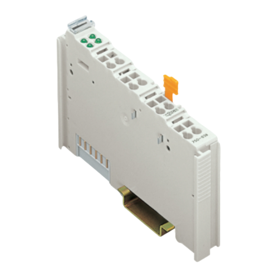
2.1.1.1 View
Provides a visual representation and labeling of the DC Drive Controller's components.
2.1.1.2 Description
Explains the core functionality and capabilities of the 750-636 DC Drive Controller.
DC Drive Controller Indicators
Indicators
Details the function of each LED on the DC Drive Controller for status and error reporting.
Operating Elements
Notes that the device has no physical operating elements; configuration is via software.
DC Drive Controller Process Image Overview
2.1.1.8.1 Overview
Provides an overview of the input and output data mapping in the process image.
Control Byte C0 and Status Byte S0
Control byte CO
Defines bits for register number, R/W access, and communication start command.
Function Description: Operating Modes and Drive Functions
Operating Modes and Drive Functions
Explains how the DC Drive Controller handles positive/negative movement and setpoint approaches.
Preset Functions
Details the two methods for referencing the drive using preset functions.
Stop and Protective Functions
Stop Functions
Details standard and exception stop functions, including ramp parameter settings.
Protective Functions
Lists monitored events such as overtemperature, overcurrent, and input failures that cause automatic shutdown.
Operating Modes for Positioning
Explains the division of operating modes into basic and auto mode for positioning.
Auto Mode Examples
Auto mode
Explains the auto mode operation, including abbreviations and examples for positioning.
Positioning with Enabled Optimization and Retry
Positioning with Enabled Optimization and Retry Not Equal to 0 (Loop Traverse)
Illustrates positioning with optimization and retry, focusing on loop traverse behavior.
Positioning with Enabled Optimization and too Short Distance
Explains positioning behavior when the distance to setpoint is too short, with retry compensation.
Positioning with Overtravel at Little Distance
Positioning with negatively initialized overtravel at too little distance
Illustrates positioning when negative overtravel is insufficient for successful approach, requiring distance adjustment.
Setpoint change on the fly
Describes how setpoint changes during active positioning affect the drive's behavior.
PWM Control during Positioning
General
Provides an overview of PWM control's role in speed and torque management during positioning.
PWM Control Phases and Drive Versions
Drive Versions Including Change to Lower Speed
Illustrates drive behavior when speed changes during positioning, focusing on shutdown distance.
PWM Control with CurrentControl_PWM
Approach without CurrentControl_PWM
Shows positioning without CurrentControl_PWM, where shutdown distance is zero or prestop is long.
Approach with CurrentControl_PWM
Illustrates positioning with CurrentControl_PWM, showing its dynamic control based on ON/OFF states.
Configuration via Parameter Channel: General Data
General Parameter Data (System Parameter Range)
Lists system parameters like TIMEOUT and NO_OF_PRMS with their addresses and access types.
Parameter Configuration: Ramp Times and Prestop Position
RampTime_START, RampTime_STOP
Configures the duration of the start and stop ramps to control motor movements.
Prestop_Pos
Sets the prestop value for positive direction optimization during positioning.
Parameter Configuration: Tolerance and Prestop Neg
Prestop_Neg
Sets the prestop value for negative direction optimization during positioning.
Target_Window
Defines the tolerance range around the setpoint position for stopping accuracy.
Parameter Configuration: Standstill, Retry, Stop Mode
Standstill_Limit, Positioning_Retry, Stopmode_PwrUp
Sets standstill speed, max retries for positioning errors, and power-up stop behavior.
Parameter Configuration: Preset Value and Overtravel
PresetValue
Sets the preset value used to initialize actual position during preset motion.
Overtravel
Defines overtravel distance for compensation and differentiates approach direction.
Parameter Configuration: Trigger Mode, Stop Mode, Direction Reversal Delay
TriggerMode_Inputs, Stop_Mode, DirectionReversal_Delay
Sets input sensitivity, braking type (idle/decelerate), and delay for direction reversal.
Parameter Configuration: PWM Duty Cycle Settings
CurrentLimit_PWM, CurrentControl_PWM
Sets duty cycles for motor control PWM signals during positioning and limit current phases.
Parameter Configuration: PWM Timing and Motion Detection
CurrentLimit_Time, MotionDetectionTimeout
Sets on-time for CurrentLimit_PWM and max wait time for encoder pulses.
Data channel for parameter exchange
Introduces the common data channel for acyclic parameter exchange via fieldbus coupler.
Parameter Channel Register Structure
Parameter data (register 56)
Describes register 56 for reading or writing parameter data, including parameter mapping.
Communication control (register 57)
Describes register 57 for parameter channel control and diagnostics.
Control and Status Bytes for Register Communication
Control byte CO
Defines bits for register number, R/W access, and communication start command.
Status byte S0
Mirrors control byte bits and indicates register communication status and register number.
Parameter Transmission Process
Read/Write Parameters (Module Specific)
Details the parameters and values for requesting and responding to module-specific data transfer.
Parameter Data Sets
Available Parameter Data Sets
Lists and describes the three types of parameter data sets and their functions.
Actual (1)
Describes the Actual parameter set, which holds current module parameters.
Parameter Data Set Management
Factory Default (3)
Explains loading manufacturer-specific parameters for a defined module state.
Password Protection
Details how to save User Settings using a password in register 31.
Changing the Parameter Data Sets
Illustrates how to access and change parameter data sets via the parameter channel.
Parameter Data Set Transfer and Commands
User Settings (2)
Describes transferring Actual (1) to User Settings (2) and restoring User Settings.
Factory Default (3)
Explains how Factory Default (3) is transferred to Actual (1) via command.
Request/Response Mechanism
Explains how commands are transferred via registers 3 and 4 for parameter channel operations.
Parameter Command Overview
Command Overview
Lists commands for user settings, factory settings, and their corresponding OK/NOK responses.
Need help?
Do you have a question about the 750-636 and is the answer not in the manual?
Questions and answers