
Related Manuals for WAGO 750-630 Series


Summary of Contents for WAGO 750-630 Series
- Page 1 Fieldbus Independent I/O Modules SSI Transmitter Interface 750-630 Manual Version 1.0.2...
- Page 2 • General Copyright 2006 by WAGO Kontakttechnik GmbH & Co. KG All rights reserved. WAGO Kontakttechnik GmbH & Co. KG Hansastraße 27 D-32423 Minden Phone: +49 (0) 571/8 87 – 0 Fax: +49 (0) 571/8 87 – 1 69 E-Mail: info@wago.com...
-
Page 3: Table Of Contents
750-630 (/xxx-xxx) [SSI Transmitter Interface] ......... 7 2.1.1.1 Variations..................7 2.1.1.2 View....................7 2.1.1.3 Description..................8 2.1.1.4 Display Elements ................9 2.1.1.5 Schematic Diagram................. 9 2.1.1.6 Technical Data ................10 2.1.1.7 Process Image ................11 2.1.1.8 Adjustable Variation 750-630/003-000 ........13 WAGO-I/O-SYSTEM 750 I/O Modules... -
Page 4: Important Comments
WAGO Kontakttechnik GmbH & Co. KG declines all liability resulting from improper action and damage to WAGO products and third party products due to non-observance of the information contained in this manual. -
Page 5: Symbols
Routines or advice for efficient use of the device and software optimization. More information References on additional literature, manuals, data sheets and INTERNET pages 1.3 Number Notation Number Code Example Note Decimal normal notation Hexadecimal 0x64 C notation Binary '100' Within ', '0110.0100' Nibble separated with dots WAGO-I/O-SYSTEM 750 I/O Modules... -
Page 6: Safety Notes
Do not use any contact spray. The spray may impair the functioning of the contact area. The WAGO-I/O-SYSTEM 750 and its components are an open system. It must only be assembled in housings, cabinets or in electrical operation rooms. Access must only be given via a key or tool to authorized qualified personnel. -
Page 7: O Modules
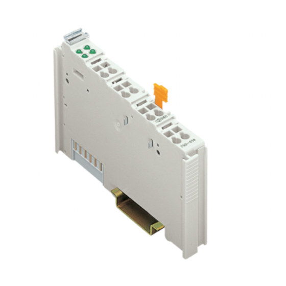
750-630/000-013 SSI/ 29Bit/ 125kHz/ Bin SSI Transmitter Interface 750-630/003-000 Variable configuration SSI Transmitter Interface 2.1.1.2 View 13 14 Status D+ D- Data contacts CL+ CL- 750-630 Power jumper contacts Fig. 2.1.1-2: SSI Transmitter Interface 750-630 g063000e WAGO-I/O-SYSTEM 750 I/O Modules... -
Page 8: Description
However, if such a case should occur, another supply module must be added. The module 750-630 and its variations can be used with all couplers/controllers of the WAGO-I/O-SYSTEM 750 (except for the economy types 750-320, -323, -324 and -327). This description is valid from hardware and software version XXXX3A05... -
Page 9: Display Elements
/ controller for 100 ms. Fig. 2.1.1-1: Display Elements Normal operation g063002x 2.1.1.5 Schematic Diagram 270pF 120R 270pF 270pF Logic 100nF 270pF 0V_EX Status 270pF 270pF 750-630 Fig. 2.1.1-2: SSI Transmitter Interface 750-630 g063001e WAGO-I/O-SYSTEM 750 I/O Modules... -
Page 10: Technical Data
II 3 G EEx nA II T4 Conformity Marking More Information Detailed references to the approvals are listed in the document "Overview Approvals WAGO-I/O-SYSTEM 750", which you can find on the CD ROM ELECTRONICC Tools and Docs (Item-No.: 0888-0412) or in the internet under: www.wago.com... -
Page 11: Process Image
Process data byte 1 0 (reserved) Process data byte 2 (MSB) 0 (reserved) 0 (reserved) 0 (reserved) Control byte C0 Bit 7 Bit 6 Bit 5 Bit 4 Bit 3 Bit 2 Bit 1 Bit 0 reserved WAGO-I/O-SYSTEM 750 I/O Modules... - Page 12 The SSI input of the module has low level when no data transfer is taking place. (SSI has swapped no power supply or wire breakage at the SSI data inputs D+ or D- or data lines). reserved WAGO-I/O-SYSTEM 750 I/O Modules...
-
Page 13: Adjustable Variation 750-630/003-000
The parameter dialog box in WAGO I/O CHECK 2 offers selection fields for the available settings of this I/O module. The following description is valid for software version 41. - Page 14 Power fail bit not active Enable Power fail bit active * default setting More Information Detailed Information about the parameterizing this module can be found in the manual for the software tool WAGO-I/O-CHECK 2 or in the Internet under: www.wago.com. WAGO-I/O-SYSTEM 750 I/O Modules...
- Page 15 750-630 (/xxx-xxx) [SSI Transmitter Interface] • 15 Adjustable Variation 750-630/003-000 WAGO-I/O-SYSTEM 750 I/O Modules...
- Page 16 WAGO Kontakttechnik GmbH & Co. KG Postfach 2880 • D-32385 Minden Hansastraße 27 • D-32423 Minden Phone: 05 71/8 87 – 0 Fax: 05 71/8 87 – 1 69 E-Mail: info@wago.com Internet: http://www.wago.com...
Need help?
Do you have a question about the 750-630 Series and is the answer not in the manual?
Questions and answers