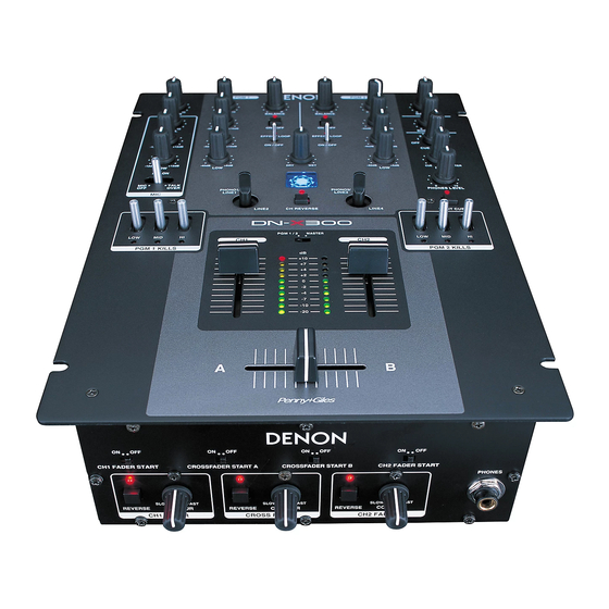
Denon DN-X300 Operating Instructions Manual
Denon dj mixer operating instructions dn-x300
Hide thumbs
Also See for DN-X300:
- Operating instructions manual (17 pages) ,
- Service manual (35 pages) ,
- Service manual (34 pages)
Table of Contents
Advertisement
Available languages
Available languages
Quick Links
Download this manual
See also:
Service Manual
Advertisement
Table of Contents

Subscribe to Our Youtube Channel
Related Manuals for Denon DN-X300


Summary of Contents for Denon DN-X300
-
Page 1: Operating Instructions
DJ MIXER DN-X300 OPERATING INSTRUCTIONS INSTRUCCIONES DE OPERACION FOR ENGLISH READERS PARA LECTORES DE ESPAÑOL PAGE 5 ~ PAGE PAGINA 11 ~ PAGINA 16... -
Page 2: Safety Instructions
In order to prevent electric shock, do not open the top cover. POUR ÉVITER LES CHOCS ÉLECTRIQUES, If problems occur, contact your DENON dealer. INTERODUIRE LA LAME LA PLUS LARGE 3. Do not place anything inside Do not place metal objects or spill liquid inside the DJ CORRESPONDANTE DE LA PRISE ET mixer. - Page 3 ENGLISH TOP PANEL DIAGRAM / DIAGRAMA DEL PANEL SUPERIOR !0 ! 0 ESPAÑOL REAR PANEL DIAGRAM / DIAGRAMA DEL PANEL POSTERIOR FRONT PANEL DIAGRAM / DIAGRAMA DEL PANEL FRONTAL #7 #6 #5 #4 #3 #2...
- Page 4 • Ta inte isär apparaten och försök inte bygga the instructions contained in this manual, om den. meets FCC requirements. Modification not expressly approved by DENON may void • Please be care the environmental aspects of battery your authority, granted by the FCC, to use disposal.
-
Page 5: Table Of Contents
Thank you very much for purchasing the DENON DN-X300 DJ MIXER. DENON proudly presents this advanced DJ MIXER to audiophiles and music lovers as a further proof of DENON’s non-compromising pursuit of the ultimate in sound quality. The high quality performance and easy operation are certain to provide you with many hours of outstanding listening pleasure. - Page 6 ENGLISH Input select switch (2) Rear panel • Switches between the PHONO/LINE and LINE inputs. • When the lever of switch is vertical position, the LINE2 or LINE4 input is selected. • When the lever of switch is slope, the PHONO1/LINE1 or PHONO2/lINE3 input is selected.
-
Page 7: Connections
“zero” and the unit is off. Take care to connect only one cable at a time. pay attention to L and R position of jacks, on both the DN-X300 and outboard gear. 5. Connect the stereo outputs to the power amplifier(s) and/or tape deck(s) and/or MD recorder(s) and/or CD recorder(s). -
Page 8: Specifications
ENGLISH SPECIFICATIONS • Phono Inputs: 2 Stereo Input Impedance 50 kΩ/kohms Level –50 dBV (3 mV) • Line Inputs: 2 Stereo Input Impedance 20 kΩ/kohms Level –14 dBV (200 mV) • EQ Control (Line): 3 Bands Control Range HI : –30 dB to +10 dB (at 16 kHz), –38 dB to +10 dB (at 20 kHz) MID : –38 dB to +10 dB (at 01 kHz) LOW : –38 dB to +06 dB (at 060 Hz) -
Page 9: Fader Start
FADER PGM2 LINE4 LINE2 FADER FADER FADER PGM1 PGM2 DN-X300 CD player (DN-S3000) (1)-2, 5 (2)-1 (1)-1 (1)-4 Channel Fader Start Turn the CH 1/2 FADER START switches #8 . Move the Channel fader @1 of CH-1 or CH-2 control all the way to the bottom. -
Page 10: Rotating Input Select Switches
ENGLISH ROTATING INPUT SELECT SWITCHES 1. Disconnect the power. 2. Remove knobs from the top panel. 3. Remove the 6 screws attaching the top panel. 4. Remove the 2 screws attaching the switch unit. 5. Rotate the switch unit to the desired location. 6. -
Page 11: Funciones Principales
DENON se siente orgulloso de presentar este avanzado DJ MIXER para los aficionados y amantes de la música como una prueba más de la búsqueda sin obligaciones de DENON de lo último en calidad de sonido. El rendimiento de alta calidad y la fácil operación sin duda le proporcionarán muchas horas de deleite con una escucha excepcional. - Page 12 Botón SPLIT CUE (2) Panel posterior • En el modo STEREO, el sonido estéreo de MASTER y CUE se enviará a ambos auriculares. Interruptor de funcionamiento de En el modo SPLIT CUE, el circuito del auricular alimentación (POWER) suministrará sonido monoaural CUE al lado •...
- Page 13 Procure conectar sólo un cable por vez. Preste atención a la posición R y L de los conectores, tanto en el DN-X300 como en el equipo externo. 5. Conecte las salidas estéreo al amplificador(es) y/o la platina(s) y/o el grabador(es) de MD y/o los grabadores de CD.
-
Page 14: Especificaciones
ESPECIFICACIONES • Entradas Phono: 2 entradas estéreo Impedancia de entrada 50 kΩ/kohmios Nivel –50 dBV (3 mV) • Entradas de línea: 2 entradas estéreo Impedancia de entrada 20 kΩ/kohmios Nivel –14 dBV (200 mV) • Control de EQ (Línea): 3 bandas Intervalo de control HI : –30 dB hasta +10 dB (a 16 kHz), –38 dB hasta +10 dB (a 20 kHz) - Page 15 PGM2 LINE4 LINE2 FADER FADER FADER PGM1 PGM2 Reproductor de CD (DN-S3000) DN-X300 (1)-2, 5 (2)-1 (1)-1 (1)-4 Comienzo de Fader de Canal Pulse los interruptores CH 1/2 FADER START #8 . Desplace el atenuador de canal @1 del control del canal 1 o el canal 2 completamente hacia abajo.
- Page 16 INTERRUPTORES SELECTORES GIRATORIOS DE LAS ENTRADAS 1. Desconecte la corriente. 2. Retire los botones del panel superior. 3. Retire los 6 tornillos que sujetan el panel superior. 4. Retire los 2 tornillos que sujetan la unidad del interruptor. 5. Haga girar la unidad del interruptor hasta la posición deseada.
- Page 17 PROFESSIONAL BUSINESS COMPANY 7-35-1 Sagamiono, Sagamihara-shi, Kanagawa 228-8505, JAPAN...
Need help?
Do you have a question about the DN-X300 and is the answer not in the manual?
Questions and answers