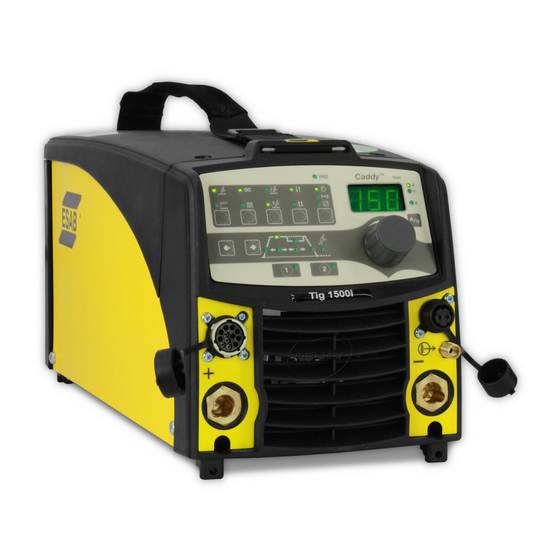
Summarization of Contents
INTRODUCTION
Design Structure of Power Source
Block diagram illustrating the power source's modular design and interconnections.
WIRING DIAGRAM
Component Description
Lists and briefly explains the function of main modules and components within the power source.
DESCRIPTION OF OPERATION
MMC Module
Describes the control panel and display board for setting and viewing welding parameters.
Power Supply Board (2AP1)
Filters mains voltage and generates internal supply voltages for the machine.
TIG System Components (10AP1)
Details the TIG board, its functions, and component layout.
Power Module System (15AP1/15AP2)
Details the power board, secondary board, their functions, and component layouts.
Control System (20AP1)
Explains the control board, its key functions, and component layout.
Component Positions (2AP1)
Illustrates the physical layout of components on the power supply board.
Component Positions (10AP1)
Shows the physical placement of components on the TIG board.
Component Positions (15AP1)
Illustrates the physical placement of components on the 15AP1 power board.
Control Board Power Supply (20AP1:1)
Details the +5 V and +2.5 V power supply circuits on the control board.
CAN Bus Communication (20AP1:2)
Explains the Controller Area Network bus for inter-unit communication and its starting sequence.
Pulse Width Modulator (20AP1:4)
Details the PWM circuit controlling frequency and pulse time for switching transistors.
Temperature Monitoring (20AP1:5)
Describes thermal overload switches for protecting the power source from overheating.
Shunt and Current Control Amplifier (20AP1:6)
Explains the shunt for current measurement and amplifier for current control.
Arc Voltage Feedback (20AP1:7)
Measures and scales arc voltage for processor input, including open-circuit voltage control.
Welding Process Control (20AP1:9)
Manages welding data and arc voltage to control welding current and hot start.
Component Positions (20AP1)
Illustrates the physical placement of components on the 20AP1 control board versions.
FAULT CODES
Fault Log and Summary
Documents faults, displays recent errors, and lists fault codes with their descriptions.
Fault Code Description
Provides detailed descriptions and corrective actions for specific power source fault codes.
SERVICE INSTRUCTIONS
ESD Precautions
Explains Electrostatic Discharge (ESD) and methods to prevent damage to sensitive components.
Service Tools and Kits
Introduces service tools like SST 3 and kits for maintenance and diagnostics.
INSTRUCTIONS
Safety and Installation
Details safety warnings and professional installation requirements for the welding power source.
OPERATION
Connections and Control Devices
Identifies and describes various connection points and control elements on the machine.
Water Connection and Overheating Protection
Explains cooling system connection, flow detection, and thermal overload protection.
MAINTENANCE
Inspection and Cleaning
Details how to inspect and clean the power source and welding torch.
FAULT-TRACING GUIDE
Recommended Checks and Inspections
Lists common faults and provides corresponding corrective actions for diagnosis.


Need help?
Do you have a question about the Cadd Tig 2200i TA33 and is the answer not in the manual?
Questions and answers