Table of Contents
Advertisement
Quick Links
INSTALLER: Leave this manual with the appliance.
CONSUMER: Retain this manual for future reference.
WARNING :
FIRE OR EXPLOSION HAZARD
Fa ilure to fo llo w sa fe ty wa rning s e xa c tly c o uld re sult
in serious injury, death, or property damage.
- Do not store or use gasoline or other fl ammable
vapors and liquids in the vicinity of this or any other
appliance.
- WHAT TO DO IF YOU SMELL GAS
• Do not try to light any appliance.
• Do not touch any electrical switch; do not use any
phone in your building.
• Leave the building immediately.
• Immediately call your gas supplier from a
neighbour's phone. Follow the gas supplier's
instructions.
• If you cannot reach your gas supplier call the fi re
department.
- Installation and service must be performed by a
qualifi ed installer, service agency or the gas supplier.
This appliance may be installed in an aftermarket
permanently located, manufactured home (USA only)
or mobile home, where not prohibited by local codes.
This appliance is only for use with the type of gas
indicated on the rating plate. This appliance is
not convertible for use with other gases, unless a
certifi ed kit is used.
This appliance is suitable for installation in a bedroom
or bed sitting room.
WARNING : If the info rma tio n in the se instruc tio ns is
not followed exactly, a fi re or explosion may result
causing property damage, personal injury or death.
180118-40
Visit www.pacifi cenergy.net for the most recent version of this manual
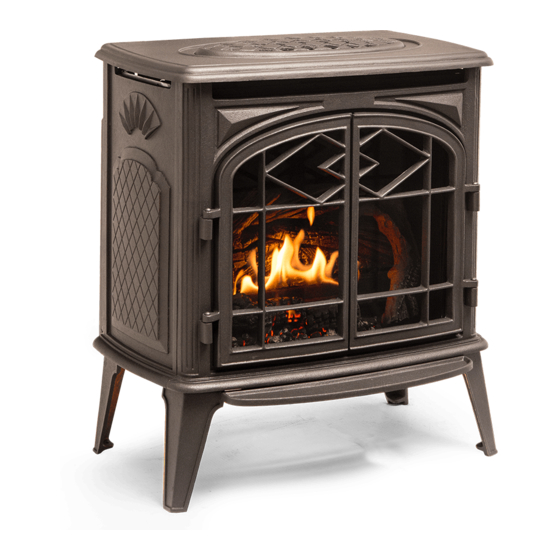
Trenton
MODEL: TRENTON
SERIES: A
FREESTANDING GAS STOVE
INSTALLATION AND
OPERATING INSTRUCTIONS
TRNT.BODYA
SERIAL #
100000457
Advertisement
Table of Contents

Subscribe to Our Youtube Channel
Related Manuals for Pacific energy Trenton


Summary of Contents for Pacific energy Trenton
-
Page 1: Operating Instructions
WARNING : If the info rma tio n in the se instruc tio ns is not followed exactly, a fi re or explosion may result MODEL: TRENTON causing property damage, personal injury or death. SERIES: A... -
Page 2: Table Of Contents
Installation ................20 Installation Requirements ............6 Venting Components ............... 21 Special Operator Note ............... 6 Trenton Gas Stove Rear Component ........22 Remote Control System ............7 Gas and Electrical Connections ..........23 System Description ............7 Gas connection ..............23 Transmitter (Remote Control with LCD Display) .... -
Page 3: Important Note For The Commonwealth Of Massachusetts
Important Note for the Commonwealth of Massachusetts From Massachusetts Rules and Regulations 248 CMR 5.08: (a) For all side wall horizontally vented gas fueled equipment installed in every dwelling, building or structure used in whole or in part for residential purposes, including those owned or operated by the Commonwealth and where the side wall exhaust vent termination is less than seven (7) feet above finished grade in the area of the venting, including but not limited to decks and porches, the following requirements shall be satisfied. -
Page 4: Caution
Caution FOR YOUR SAFETY - Do not install or operate your Trenton gas stove without first reading and understanding this manual. Any installation or operational deviation from the following instructions voids the Pacific Energy Fireplaces Warranty and may prove hazardous. -
Page 5: Safety
Owner information Safety Due to high temperatures, this gas stove should be located out of traffic and away from furniture and draperies. Children and adults should be alerted to the hazards of high surface temperatures and should stay away to avoid burns or clothing ignition. -
Page 6: Manufactured (Mobile) Homes
Owner information Manufactured (Mobile) Homes In some jurisdictions, the Trenton gas stove may be installed in Manufactured Homes after the “first sale”. Consult local codes for approval. The gas stove must be fastened in place. Install in accordance with the current standard Mobile Homes, CAN/CSA Z240 MH (in CANADA), and the Manufacturer’s Home Construction and Safety Standard, Title 24 CFR, Part 3280 or the current Standard... -
Page 7: Remote Control System
Owner information Remote Control System System Description The Profl ame Remote Control System consists of three elements: 1. Profl ame Remote Transmitter. 2. Profl ame Integrated Fireplace Control (IFC) module. 3. A wiring harness to connect the IFC to the gas valve and stepper motor. Transmitter (Remote Control with LCD Display) The Profl... -
Page 8: Temperature Indication Display
If the batteries of the receiver or remote transmitter are low or depleted, the gas stove can be turned off manually using ON/OFF switch located on battery holder at the rear of the Trenton (Figure 66 on page 32). This will bypass the remote transmitter. -
Page 9: Remote Flame Control
Owner information Remote Flame Control The Proflame has six (6) flame levels. With the system turned on, and the flame level at maximum in the gas stove, press the down arrow key once to reduce the flame height by one step until the flame is turned off. The up arrow key will increase the flame height each time it is pressed. -
Page 10: Comfort Fan Speed Control
Owner information Comfort Fan Speed Control If the gas stove is equipped with a hot air circulating fan, the speed of the fan can be controlled by the Profl ame System. The fan speed can be adjusted through six (6) speeds. To activate this function use the Mode Key (Figure 1) to index to the fan control icon (Figure 13). -
Page 11: Low Battery Power Detection
Owner information Low Battery Power Detection Remote Transmitter The life span of the remote control batteries depends on various factors: quality of the batteries used, the number of ignitions of the gas stove, the number of changes to the room thermostat set point, etc. -
Page 12: Maintenance
Owner information Maintenance Turn off gas and electrical power supply (if applicable) and allow ample time for the gas stove to cool before servicing gas stove. It is recommended that the gas stove and its venting should be inspected at least once a year by a qualified service person. -
Page 13: Lighting Instructions
Owner information Lighting Instructions FOR YOUR SAFETY READ BEFORE LIGHTING - Immediately call your gas supplier from a neighbour's phone. Follow WARNING: If you do not follow these instructions exactly, a the gas supplier's instructions. fire or explosion may result causing property damage, - If you cannot reach your gas supplier, call the fire department. -
Page 14: Trenton Gas Stove Dimensions
Installer information Trenton Gas Stove Dimensions Dimensions Height 30 5/ 8 inches Width 26 3/4 inches Depth 21 15/16 inches Height to center of Flue Outlet 24 inches 26 3/4” 21 15/16” 30 5/8” 24” Figure 20: Trenton dimensions. TRNT.BODYA... -
Page 15: Clearances To Combustibles
CLEARANCES TO COMBUSTIBLE MATERIAL requirement is that 4” the floor be stable Horizontal venting 1” and strong enough to Horizontal venting “ support the stove Vertical venting 4” 4” 1” Figure 22: Trenton common locations & minimum allowances. 100000457 180118-40 TRNT.BODYA... -
Page 16: Vent Terminal Clearances
Installer information Vent Terminal Clearances Minimum clearances to the vent terminal must be maintained as shown in Figure 23 and the Roof Pitch Table. Measure clearances to the nearest edge of termination hood. NOTE: Vent terminal must not be recessed VENT TERMINAL MINIMUM CLEARANCES TO ADJACENT STRUCTURES NOTE: LOCAL CODES OR REGULATIONS MAY REQUIRE... -
Page 17: Trenton Co-Axial Venting Chart
3’ be used. Otherwise, the regular terminal can be used. 2’ 1’ No venting options 1’ 2’ 3’ 4’ 5’ 6’ 7’ 8’ 9’ 10’ 11’ 12’ 13’ 14’ 15’ 16’ Figure 25: Trenton venting chart examples. 100000457 180118-40 TRNT.BODYA... -
Page 18: Co-Linear Venting
fl ush Figure 26 with the cover or other material. 2. Positioning the TN24 so that it and the adapter are located outside of the existing fi replace opening. Figure 26: Trenton co-linear venting confi guration. TRNT.BODYA 100000457 180118-40... -
Page 19: Optional Direct Vent Termination "Snorkel
Installer information Optional Direct Vent Termination “Snorkel” 13” 7” 1” 4 1/4” 33 1/4” 4” 6 5/8” Front view Side view Note: For proper operation, the Snorkel must be oriented so that the vent inlet and outlet are located at the 24 1/2”... -
Page 20: Installation
Installer information Installation Attachment points Attachment points and drain ports Figure 28: Fastening the snorkel. Figure 29: Caulking the snorkel. Installation: The Snorkel can be attached to an exterior wall using 4 supplied screws. Be sure to position the Snorkel correctly so that the drain ports are located at the bottom of the unit. Exterior facing or siding can butt right up to the sides of the unit and can extend up to 1”... -
Page 21: Venting Components
Installer information Venting Components NOTE: Mixing venting components from different manufacturers is inadvisable. Description Metal-Fab® Security Selkirk DuraVent EXCELDirect® Sure-Seal Secure Vent™ Direct-Temp™ DirectVent Pro® Galvanize Black Galvanized Black Galvanized Black Galvanized Black Galvanized Black 6” Pipe Length 4DL6 4DL6B 4D6B SV4L6 SV4LB6... -
Page 22: Trenton Gas Stove Rear Component
Figure 32: Co-axial venting components. Trenton Gas Stove Rear Component Right blower fan Right blower fan Battery holder location Gas supply Control connection module Electrical plug-in connection Gas valve Venturi adjustment Figure 33: Trenton rear side components. TRNT.BODYA 100000457 180118-40... -
Page 23: Gas And Electrical Connections
34 of the manual for requirement of the gas supply. Electrical connection An IEC power cord is provided for connection to a standard wall outlet. Note: Gas connector is not included. Figure 34: Trenton gas & electrical connections. 100000457 180118-40 TRNT.BODYA... -
Page 24: Packaging
The glass door and screen must be removed before the log set and embers can be accessed. Figure 35: Trenton gas stove with packaging. Safety screen removal Cover in raised position Figure 36: Trenton top cover. -
Page 25: Log Set Pieces
Installer information 1. Remove the safety screen. 2. Remove the wing nut bolts (Figure 39) securing the glass door retainer frame to the gas stove frame and tilt the glass door so that it can be removed (Figure 40). 3. Remove the glass door together with the retainer frame that it is affixed to. Log set pieces Figure 41: Number one log. -
Page 26: Log Set Installation
Installer information Log Set Installation Installation of log set 1. Fill burner tray (Figure 44) with embers so that the baskets are filled and overflowing the burners’ front row (Figure 45). Reserve a small amount of embers for final placement. 2. - Page 27 Installer information Inset of tab. Figure 48: 3rd log placement. 4. Position 3rd log as shown in Figure 48 making sure that the log does not cover the holes of the back row of the burner. The 3rd log has a hole in its underside which will fit onto a protruding tab on the burner (Inset of tab).
-
Page 28: Glass Door Installation
Installer information Figure 51 shows the burners’ back row as not being covered by the logs. At this time, the small amount of embers reserved at the beginning of log placement can be used to fill any left over spaces. NOTE: Although it is permissible to place a few embers between the back burner and the 3rd and 4th logs in order to hide the back... -
Page 29: Safety Screen Installation
Installer information Safety Screen Installation Safety screen installation The screen mesh is positioned between the glass door and the doors. It's purpose is to provide protection from the heat radiating from the glass door. The screen has a front side and a rear side and must be oriented correctly for a proper fit. - Page 30 Installer information The bottom edge of the screen mesh must fi t fi rmly into the channel provided for it Fire box Do o r in the fi re box frame. Figure 59 shows the side side location of the screen mesh channel. The screen mesh top holder (Figure 60) positions the screen mesh so that there is the correct distance between the screen...
-
Page 31: Accent Lighting Glass Plates
Trenton Gas Stove Figure 1 on page 7. The glass plate tray is located underneath the Trenton (Figure 62) and is held in place by two wing nuts - one on each side of the tray. -
Page 32: Ifc Module
Initializing the System for the fi rst time 1. Install 4 AA batteries into the Trenton battery holder (Figure 64) located on the rear side of the Trenton. Make sure that the selection switch on the switch cover is on the “Remote” setting. -
Page 33: Damper Adjustment
flame). + = open - = c lo se d Figure 68: Trenton damper adjustment. Venturi Adjustment Venturi adjustment is accessible through an opening in the rear cover. See location on Figure 33 on page 22. -
Page 34: Gas Supply
Check local codes for additional requirements. Turn on the gas supply and check that all connections are tight and leak free. Gas Pressure Check Gas pressure requirements Trenton Input Pressure Natural Gas Propane Orifice Output... -
Page 35: Gas Pressure Testing Procedure
Pilot Flame Adjustment The pilot flame level can be adjusted by turning the adjustment screw, using a flat-tip screwdriver, as seen on the valve in Figure 72. Figure 70: Trenton pilot assembly. Main gas Pilot Pilot flame level solenoid... -
Page 36: Propane Conversion
To switch the pressure modulator, follow the instructions that are provided with the conversion kit. Figure 73: Trenton pilot. To change the orifi ces you are required to remove the mesh and glass doors, log-set, embers and burner. Please refer to the appropriate sections of this manual and follow instructions on how to correctly remove these components. -
Page 37: Replacement Parts
Trenton Control Tray Complete ..... 80000608 Trenton Panel Set Painted ......80001867 Trenton Burner ..........80002056 Trenton Log Set with Embers ....... 80000627 Trenton Blower Right ........80000905 Trenton Blower Left ........80000904 Trenton Light Housing with Bulb ....80000626 Trenton Decorative Tinted Glass Kit ..... -
Page 38: Wiring Diagram
Installer information Wiring Diagram LAMP COMFORT C a utio n: La b e l a ll wire s p rio r to d isc o nne c tio n whe n se rvic ing c o ntro ls. Wiring e rro rs c a n c a use imp ro p e r a nd d a ng e ro us o p e ra tio n. -
Page 39: Rating Label
Installer information Rating Label T he Ra ting la b e l - a s sho wn - is lo c a te d o n the re a r o f the g a s sto ve . 100000457 180118-40 TRNT.BODYA... - Page 40 © 2018 Copyright Pacific Energy Fireplace Products LTD Reproduction, adaptation, or translation without prior written permission is prohibited, except as allowed under the copyright laws. For technical support, please contact your retailer Web site: www. pacificenergy.net 2975 Allenby Rd., Duncan, BC V9l 6V8 Printed in Canada...
Need help?
Do you have a question about the Trenton and is the answer not in the manual?
Questions and answers