Advertisement
PIR EXTERIOR DE ZONA DUAL / Manual de instrucciones
1
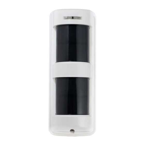
PARTS DESCRIPTION DESCRIPCIÓN DE LAS PIEZAS
Cover
Tapa
A
A
D
Sensor
B
E
C
M
A. Operation LED
LED operacional
B. Lens
Lente
C. Cover locking screw
Tornillo de bloqueo de la tapa
D. Adjustment lever
Palanca de ajuste
E. Sensitivity adjustment
Ajuste de sensibilidad
F. Body locking screw
Tornillo de bloqueo del cuerpo
Accessories
Accesorios
O
P (1 pc, 1 pza.)
TX-114TR/114SR (1 pc, 1 pza.)
TX-114FR (2 pcs, 2 pzas.)
T (2 pcs, 2 pzas.)
TX-114TR/114FR/114SR
DUAL ZONE OUTDOOR PIR / Instruction Manual
TX-114TR
F
G
H
A
I
D
E
J
Body unit + Mounting base
Unidad del cuerpo + Base de montaje
Body unit
Unidad del cuerpo
K
G. Wiring hole
Orificio del cableado
H. Terminals
Terminales
I. Front tamper switch
Interruptor tamper frontal
J. Setting switches
Interruptores de ajuste
K. Space for battery & transmitter
Espacio para la batería y el transmisor
Q TX-114TR/114FR
(2 pcs, 2 pzas.)
S (1 pc, 1 pza.)
U (1 pc, 1 pza.)
TX-114FR
Upper Sensor
Sensor superior
I
J
Lower Sensor
Sensor inferior
Mounting base
Base de montaje
N
O. Area masking sheet
Lámina de enmascaramiento de área
P. Adhesive sheet
Lámina adhesiva
Q. Mounting screw with seal W
R TX-114SR
Tornillo de montaje con sello W
(1 pc, 1 pza.)
R. Mounting screw
Tornillo de montaje
S. Battery holder
Soporte de batería
T. Battery Leads
Cables para la batería
U. Back Tamper killer
Tamper trasero killer
1
TX-114SR
A
Sensor
D
I
E
J
Body unit
Unidad del cuerpo
K
L
L. Wire color
Red
: Battery input (+)
Black : Battery input (-)
Blue
: Alarm signal
Green : Tamper signal
Color del cable
Rojo : Entrada de la batería (+)
Negro : Salida de la batería (-)
Azul
: Señal de alarma
Verde : Señal tamper
M. Back tamper switch
Interruptor tamper trasero
N. Back tamper actuator
Actuador tamper trasero
Advertisement
Table of Contents

Related Manuals for Takex TX-114SR


Summarization of Contents
DETECTION AREA
PATTERNS OF COVERAGE
Illustrates various detection coverage patterns.
AREA ADJUSTMENT [Horizontal adjustment]
How to adjust the sensor's horizontal detection area.
Fine adjustment [Wall detection]
Fine-tuning for wall-mounted detection.
ADJUSTMENT
Alarm output selectable
Selectable alarm output type.
Pulse count selectable
Selectable pulse count for detection.
Tamper output selectable
Option to select tamper output type.
Warm up period
Initial sensor stabilization period.
Trouble alarm
Alarm signal for functional issues.
Front tamper signal (Cover removal)
Tamper signal when cover is detached.
Back tamper signal (Whole unit removal)
Tamper signal when unit is detached.
INSTALLATION
Wall Mounting
Instructions for wall mounting the sensor.
Pole Mounting
Instructions for mounting the sensor on a pole.
Need help?
Do you have a question about the TX-114SR and is the answer not in the manual?
Questions and answers