Table of Contents
Advertisement
Quick Links
BATTERY OPERATED PHOTOELECTRIC BEAM SENSOR
TXF-125E-KH : OUTDOOR 100m (330ft)
Thank you for purchasing this product. Before using the product, please read this instruction manual to ensure correct operation.
This product is designed to be installed into the housing (sold separately) for use. Make sure to install this product into the housing
for use.
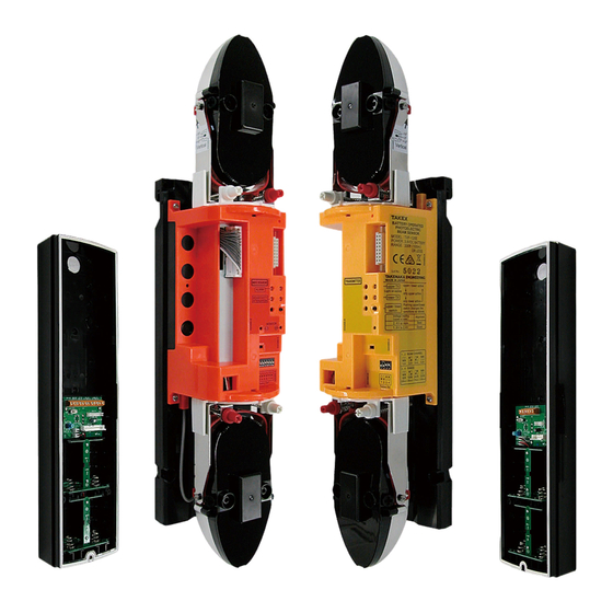
This unit is a battery operated photoelectric beam sensor consisting of a
transmitter and a receiver.
The direct path between the transmitter and the receiver forms the
detection line. When this detection line is interrupted (light is obstructed for
0.05 to 0.5sec. or more), the receiver outputs a signal.
The battery operated design allows this unit to operate without an external
power supply over a long period of time. The battery power also can be
shared with a wireless transmitter.
In order to ensure that the detection line has sufficient margin of sensitivity,
adjust the direction of the light beams before putting the system into
operation. Providing sufficient margin of sensitivity reduces the malfunction
caused by dense fog, heavy rain, frost, snow, and other such weather
conditions.
(1) WIDE BEAM
As is the case with the wired system, increasing the
vertical beam pitch together with the 4 beam
simultaneous interruption system significantly reduces
false alarms from birds or fallen leaves, etc.
(2) QUAD HIGH POWER BEAM
The beam power is 100 times greater than the
minimum requirement.
The beam distance is 10 times longer than the
described specification.
This high power beam ensures high reliability against
harsh conditions such as fog, snow and heavy rain.
(3) REDUCE COSTS
By combining a wireless transmitter, external wiring
becomes unnecessary, which can substantially reduce
wiring material costs and related work.
In addition, this unit realizes longer battery life due to
its low current consumption.
(4) DETECTION DISTANCE SELECTABLE
4 detection distances are selectable within a single
unit [100m(330 ) / 75m(247 ) / 50m(165 ) / 25m(82 )]
(5) BATTERY SHARING FUNCTION
This function integrated in the sensor enables battery
sharing with a wireless transmitter. Low battery
output voltage is adjustable by volume switch.
(6) ECOLOGY
Environment friendly.
RoHS compliant. (2011/65 /EU+(EU)2015/863)
Instruction Manual
(7) DUAL RING SIGHT
(8) TARGET COLOR
(9) INCREASED ANGLE ADJUSTMENT
(10) WIRELESS ALIGNMENT CHECKER
(11) LIGHTNING PROTECTION
①
Enables clear view for easy beam alignment.
The vivid color of the internal structure can be
recognized easily at distance during the beam
alignment procedure.
The color differs between transmitter and receiver
for easy installation and checking.
±20° vertical adjustment to adapt to changes in
elevation for maximum flexibility
<Reference> This unit can be installed in a place
with a height difference of 18m(59 ) or less when
the protection distance is 50m(165 ), and 36m(118 )
or less when it is 100m(330 ).
Enables easy and accurate beam alignment.
(Sold separately)
This unit is insusceptible to induced lightning
because of its battery operated system.
Advertisement
Table of Contents

Subscribe to Our Youtube Channel
Related Manuals for Takex TXF-125E-KH


Summary of Contents for Takex TXF-125E-KH
- Page 1 BATTERY OPERATED PHOTOELECTRIC BEAM SENSOR TXF-125E-KH : OUTDOOR 100m (330ft) Instruction Manual Thank you for purchasing this product. Before using the product, please read this instruction manual to ensure correct operation. This product is designed to be installed into the housing (sold separately) for use. Make sure to install this product into the housing for use.
-
Page 2: Main Unit
— — (1) MAIN UNIT (2) ACCESSORIES ②... - Page 3 (3) NAMES OF OPERATION SECTION 5 6 7 8 (4) NAMES OF TERMINAL SECTION : : Be sure to observe We categorize these precautions throughout the manual using the following symbols. Warning electrical shock, or malfunction of the device. If the following events occur, turn off the power of the unit immediately, and ask the place of purchase for repair.
- Page 4 Caution Do not apply impact to the unit. Strong impact may result in performance deterioration and/or damage to the unit. The unit may not operate properly near devices that generate a strong electric or magnetic field. Also, devices near the unit may not operate properly due to the magnetic field and/or magnetism generated from the unit.
-
Page 5: Mounting Height
Cautions when using the outdoor photoelectric beam sensor (Regular maintenance) PROTECTION DISTANCE AND LIGHT BEAM COVERAGE MOUNTING HEIGHT OPTICAL AXIS ADJUSTMENT RANGE The optical axis may be shielded depend- ing on the shape of the housing and mounting surface. Check the optical axis range carefully and start installation before use. - Page 6 For 2 level straight line protection, set the TAKEX. frequency of 2 adjacent sensors to the channels at • Consult with TAKEX distributor or TAKEX regional intervals and provide up to 2 spans. Also, office about the frequency selection for installations not perform a sufficient operation check before actual mentioned in this instruction manual.
-
Page 7: About Batteries
(1) CHECKING SPACE FOR WIRELESS TRANSMITTER (2) ABOUT BATTERIES (3) MOUNTING WIRELESS TRANSMITTER (4) WIRELESS TRANSMITTER WIRING ① ② ⑤ ⑥ − ① ② ③ ④ ⑤ ⑥ ⑦ ⑧ ⑪ ⑫ − ⑦... -
Page 8: Mounting Batteries
(5) SETTING LOW BATTERY OUTPUT VOLTAGE Warning When sharing the battery power of TXF-125E-KH with a wireless transmitter, don’t insert batteries into the wireless transmitter. Failure to follow this may result in fire or explosion. Wireless trasmitter is not incorporated into this unit at the time of shipment from the manufacturer. - Page 9 ATTACHING TO THE TOWER × × × ⑨...
-
Page 10: Names And Functions
Adjusting the optical axis correctly ensures a sufficient sensitivity margin that increases resistance to dense fog, snow, and heavy rain, establishing a highly reliable intrusion alarm system. (1) NAMES AND FUNCTIONS Names of the Optical Unit Reflector Section Horizontal/Vertical Angle Adjustment Method Double Ring Alignment Mechanism, visible from the view finder Sequence of adjustment ⑩... - Page 11 (2) ALIGNMENT MECHANISM ⑪...
- Page 12 Names of operation section When adjusting beam alignment, please select “Mode selector” to “Alignment” on both the transmitter and the receiver in order to adjust the beam alignment accurately. ① ① ① ① ② ...
-
Page 13: Sound Check
(3) SOUND CHECK The sound check function indicates the light reception level by using high and low pitched tones. The sound check function is only installed on the receiver. First, check only the transmission and reception on the upper level , and then check only the transmission and reception on the lower level. - Page 14 (4) MONITOR OUTPUT VOLTAGE More accurate adjustment of the optical axis can be achieved by checking the light reception level value using the voltage of the monitor output. First, check only the transmission and reception on the upper level , and then check only the transmission and reception on the lower level.
- Page 15 (5) WIRELESS ALIGNMENT CHECKER: ER-02 (SOLD SEPARATELY) The wireless alignment checker ER-02 can be used to check the monitor output voltage both on the transmitter and receiver, which enables even one person to easily complete the correct optical axis adjustment. Also, the light reception level can be checked during optical axis adjustment because the monitor output voltage can be checked.
-
Page 16: Battery Saving Function
(1) MODULATION FREQUENCY CHANGEOVER FUNCTION (2) DETECTION PROTECTION DISTANCE CHANGEOVER FUNCTION (3) RESPONSE TIME ADJUSTMENT FUNCTION 〔 〕 (1) If the interruption time is shorter than the response time, the obstructing object is not detected. (2) In areas where there are large objects fluttering in the wind and obstruct the optical axis (e.g., birds, newspaper, and cardboard), set the response time slightly slower according to the installation condition. - Page 17 (5) REPEAT OUTPUT FUNCTION Note: Only installed on the receiver (6) SOUND CHECK FUNCTION (7) UPPER/LOWER CHANGEOVER FUNCTION Note: Installed on the transmitter and the receiver (8) SENSITIVITY ATTENUATION SIGNAL FUNCTION (9) LOW BATTERY DISPLAY FUNCTION (10) WIRELESS ALIGNMENT CHECKER CONNECTION FUNCTION ⑰...
-
Page 18: Maintenance
(11)MODE SELECTOR FUNCTION accurately. ※ To clean the device, use a soft, wet cloth and then wipe off any water drops. Maintenance If the device is particularly dirty, dip the soft cloth in the water that contains a weak neutral detergent. Wipe the device gently with the cloth, then wipe off any detergent that remains. - Page 19 ( ( Specifications and design are subject to change without prior notice. ⑲...
- Page 20 Limited Warranty : TAKEX products are warranted to be free from defects in material and workmanship for 12 months from original date of shipment. Our warranty does not cover damage or failure caused by Acts of God (including inductive surge by lightning), abuse, misuse, abnormal usage, faulty installation, improper maintenance or any repairs other than those provided by TAKEX.
Need help?
Do you have a question about the TXF-125E-KH and is the answer not in the manual?
Questions and answers