Advertisement
PIR EXTERIOR DE ZONA DUAL / Manual de instrucciones
1
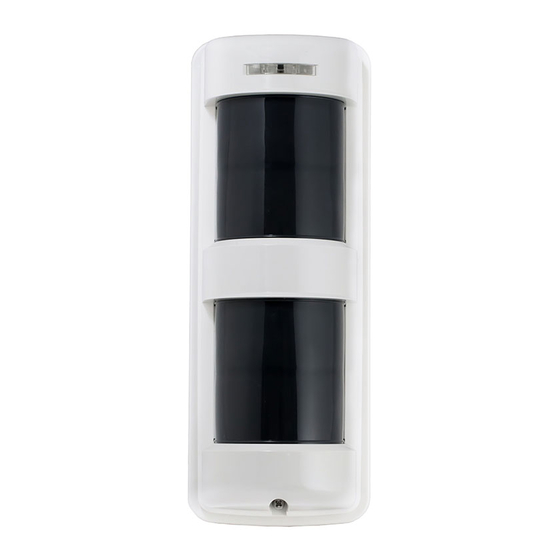
PARTS DESCRIPTION DESCRIPCIÓN DE LAS PIEZAS
Cover
Tapa
A
A
D
Sensor
B
E
C
M
A. Operation LED
LED operacional
B. Lens
Lente
C. Cover locking screw
Tornillo de bloqueo de la tapa
D. Adjustment lever
Palanca de ajuste
E. Sensitivity adjustment
Ajuste de sensibilidad
F. Body locking screw
Tornillo de bloqueo del cuerpo
Accessories
Accesorios
O
P (1 pc, 1 pza.)
TX-114TR/114SR (1 pc, 1 pza.)
TX-114FR (2 pcs, 2 pzas.)
T (2 pcs, 2 pzas.)
TX-114TR/114FR/114SR
DUAL ZONE OUTDOOR PIR / Instruction Manual
TX-114TR
F
G
H
A
I
D
E
J
Body unit + Mounting base
Unidad del cuerpo + Base de montaje
Body unit
Unidad del cuerpo
K
G. Wiring hole
Orificio del cableado
H. Terminals
Terminales
I. Front tamper switch
Interruptor tamper frontal
J. Setting switches
Interruptores de ajuste
K. Space for battery & transmitter
Espacio para la batería y el transmisor
Q TX-114TR/114FR
(2 pcs, 2 pzas.)
S (1 pc, 1 pza.)
U (1 pc, 1 pza.)
TX-114FR
Upper Sensor
Sensor superior
I
J
Lower Sensor
Sensor inferior
Mounting base
Base de montaje
N
O. Area masking sheet
Lámina de enmascaramiento de área
P. Adhesive sheet
Lámina adhesiva
Q. Mounting screw with seal W
R TX-114SR
Tornillo de montaje con sello W
(1 pc, 1 pza.)
R. Mounting screw
Tornillo de montaje
S. Battery holder
Soporte de batería
T. Battery Leads
Cables para la batería
U. Back Tamper killer
Tamper trasero killer
1
TX-114SR
A
Sensor
D
I
E
J
Body unit
Unidad del cuerpo
K
L
L. Wire color
Red
: Battery input (+)
Black : Battery input (-)
Blue
: Alarm signal
Green : Tamper signal
Color del cable
Rojo : Entrada de la batería (+)
Negro : Salida de la batería (-)
Azul
: Señal de alarma
Verde : Señal tamper
M. Back tamper switch
Interruptor tamper trasero
N. Back tamper actuator
Actuador tamper trasero
Advertisement
Table of Contents

Related Manuals for Takex TX-114FR


Summarization of Contents
1 Parts Description
Key Component Identification
Identifies major parts like sensors, LEDs, switches, and connectors.
Wire Color Legend
Explains the function of each wire color for electrical connections.
2 Precautions
Installation and Environmental Guidelines
Advises on mounting height, orientation, and avoiding environmental interference.
3 Detection Area
Coverage Patterns
Illustrates wide angle and wall detection patterns.
Detection Zone Adjustment
Explains how to adjust detection zones for different scenarios.
4 Detection Distance Adjustment
Setting Detection Range
How to set detection distance by adjusting the downward zone angle.
Factors Affecting Detection Performance
Discusses environmental factors like temperature and object path affecting performance.
5 Area Masking Sheet
Masking Zone Application
Instructions on cutting and applying the sheet to modify detection zones.
6 Adjustment
Switch Settings and Configuration
Configuration options for alarm output, pulse count, and tamper settings.
Tamper Switch Functionality
Details on front and back tamper switch operations and signals.
Wiring and Terminal Configuration
Diagrams and explanations for common and separate battery wiring setups.
8 Installation
Assembling and Mounting
Guides for assembling the unit and mounting it on walls or poles.
9 External Dimensions
Model Dimensions
Detailed physical measurements for the TX-114TR/114FR and TX-114SR models.
Troubleshooting
Problem Resolution Guide
Table detailing common problems and their corrective actions.
Interpreting LED Status
Explains the meaning of LED behavior during different operational states.
Need help?
Do you have a question about the TX-114FR and is the answer not in the manual?
Questions and answers