
Related Manuals for H3C LS-3100-16TP-EI-H3-A-O


Summary of Contents for H3C LS-3100-16TP-EI-H3-A-O
- Page 1 H3C S3100 Series Ethernet Switches Installation Manual Hangzhou H3C Technologies Co., Ltd. http://www.h3c.com Manual Version: 20080115-C-1.04...
- Page 2 Copyright © 2007-2008, Hangzhou H3C Technologies Co., Ltd. and its licensors All Rights Reserved No part of this manual may be reproduced or transmitted in any form or by any means without prior written consent of Hangzhou H3C Technologies Co., Ltd. Trademarks H3C, , Aolynk,...
-
Page 3: About This Manual
About This Manual Related Documentation In addition to this manual, each H3C S3100 Series Ethernet Switches documentation set includes the following: Manual Description H3C S3100 Series Ethernet Switches It is used for assisting the users in data Operation Manual configurations and typical applications. H3C S3100 Series Ethernet Switches It is used for assisting the users in using Command Manual... - Page 4 Chapter Contents 7 Appendix Lightning Protection of the Introduces lightning protection of S3100 Switch Series Ethernet Switches. Conventions The manual uses the following conventions: I. GUI conventions Convention Description Button names are inside angle brackets. For example, click < > <OK>.
-
Page 5: Table Of Contents
Installation Manual H3C S3100 Series Ethernet Switches Table of Contents Table of Contents Chapter 1 Product Introduction ....................1-1 1.1 Overview ..........................1-1 1.1.1 S3100-SI Series Ethernet Switches ................ 1-1 1.1.2 S3100-EI Series Ethernet Switches ................ 1-2 1.2 Introduction to S3100-SI Series Ethernet Switches............1-3 1.2.1 S3100-26T-SI ...................... - Page 6 Installation Manual H3C S3100 Series Ethernet Switches Table of Contents Chapter 3 Installation ........................3-1 3.1 Installing a Switch ......................3-1 3.1.1 Cabinet Mounting ....................3-1 3.1.2 Desk Mounting ...................... 3-11 3.1.3 Wall Mounting......................3-11 3.1.4 Magnet Mounting....................3-13 3.2 Installing an Expansion Interface Module................ 3-15 3.3 Connection of Power Cable and Grounding Cable............
- Page 7 Installation Manual H3C S3100 Series Ethernet Switches Table of Contents...
-
Page 8: Chapter 1 Product Introduction
Installation Manual H3C S3100 Series Ethernet Switches Chapter 1 Product Introduction Chapter 1 Product Introduction 1.1 Overview The H3C S3100 Series Ethernet Switches are high-performance, high-density, easy-to-install, NMS-manageable intelligent Ethernet switches which support wire-speed Layer 2 switching. Table 1-1 lists the models of the H3C S3100 Series Ethernet Switches. Table 1-1 Models of the H3C S3100 Series Ethernet Switches Name Subseries... -
Page 9: S3100-Ei Series Ethernet Switches
Installation Manual H3C S3100 Series Ethernet Switches Chapter 1 Product Introduction Table 1-3 H3C S3100-C-SI Series Ethernet Switches Number of Number of Number of 10/100 Mbps expansion console Model Power input slots ports electrical ports S3100-26C-SI AC input for AC-powered S3100-16C-SI switches. -
Page 10: Introduction To S3100-Si Series Ethernet Switches
Installation Manual H3C S3100 Series Ethernet Switches Chapter 1 Product Introduction Table 1-5 Models of the H3C S3100-C-EPON-EI Series Ethernet Switches Number Number of Number of 10/100 Number of Power 1000 Mbps Model Mbps expansion input uplink console electrical slots PON ports ports ports... -
Page 11: S3100-16T-Si
Installation Manual H3C S3100 Series Ethernet Switches Chapter 1 Product Introduction II. Rear panel Figure 1-2 shows the rear panel of an S3100-26T-SI Ethernet switch. (1) AC power socket (2) Grounding screw Figure 1-2 Rear panel of an S3100-26T-SI Ethernet switch III. -
Page 12: S3100-8T-Si
Installation Manual H3C S3100 Series Ethernet Switches Chapter 1 Product Introduction Note: For details about LEDs on the front panel, refer to section 1.4.1 “Front Panel LEDs of the S3100-SI/S3100-TP-PWR-EI/S3100-C-EPON-EI Series”. II. Rear panel Figure 1-4 shows the rear panel of an S3100-16T-SI Ethernet switch. (1) AC power socket (2) Grounding screw Figure 1-4 Rear panel of an S3100-16T-SI Ethernet switch... - Page 13 Installation Manual H3C S3100 Series Ethernet Switches Chapter 1 Product Introduction (1) Power LED (2) A/L LED (3) D/S LED (4) Port status LED, left (yellow) (5) Port status LED, right (green) (6) 10/100 Base-TX port (7) 10/100/1000 Base-T port (8) Console port (9) LINK LED (green) (10) ACT LED (yellow)
-
Page 14: S3100-26C-Si
Installation Manual H3C S3100 Series Ethernet Switches Chapter 1 Product Introduction 1.2.4 S3100-26C-SI Both AC-powered switches and DC-powered switches are available to this model. I. Front panel S3100-26C-SI Ethernet switches each provide twenty-four auto-sensing 10/100Base-TX Ethernet ports, two expansion slots, and one console port. S3100-26C-SI Ethernet switches have the same front panel, as shown in Figure 1-7. -
Page 15: S3100-16C-Si
Installation Manual H3C S3100 Series Ethernet Switches Chapter 1 Product Introduction Figure 1-9 shows the rear panel of an S3100-26C-SI DC-powered Ethernet switch. (1) DC input terminal block (2) Grounding screw Figure 1-9 Rear panel of an S3100-26C-SI DC-powered Ethernet switch III. - Page 16 Installation Manual H3C S3100 Series Ethernet Switches Chapter 1 Product Introduction Note: With a PoE card inserted in one expansion slot, an S3100-16C-SI Ethernet switch will be a powered device (PD). In this case, the other expansion slot becomes unavailable. For details about LEDs on the front panel, refer to section 1.4.1 “Front Panel LEDs of the S3100-SI/S3100-TP-PWR-EI/S3100-C-EPON-EI Series”.
-
Page 17: S3100-8C-Si
Installation Manual H3C S3100 Series Ethernet Switches Chapter 1 Product Introduction 1.2.6 S3100-8C-SI Both AC-powered switches and DC-powered switches are available to this model. I. Front panel S3100-8C-SI Ethernet switches each provide eight auto-sensing 10/100Base-TX Ethernet ports, one expansion slot, and one console port. S3100-8C-SI Ethernet switches have the same front panel, as shown in Figure 1-13. -
Page 18: Introduction To S3100-Ei Series Ethernet Switches
Installation Manual H3C S3100 Series Ethernet Switches Chapter 1 Product Introduction Figure 1-15 shows the rear panel of an S3100-8C-SI DC-powered Ethernet switch. (1) DC input terminal block (2) Grounding screw Figure 1-15 Rear panel of an S3100-8C-SI DC-powered Ethernet switch III. - Page 19 Installation Manual H3C S3100 Series Ethernet Switches Chapter 1 Product Introduction (1) Auto-sensing 10/100Base-TX port Speed LED (green) (2) Auto-sensing 10/100Base-TX port (3) Combo port Speed LED (green) (4) Auto-sensing 10/100/1000Base-T port (5) Console port (6) 100/1000Base-X SFP port (7) LINK/ACT LED (green) (8) Power LED (PWR) Figure 1-16 Front panel of an S3100-26TP-EI Ethernet switch Note:...
-
Page 20: S3100-16Tp-Ei
Installation Manual H3C S3100 Series Ethernet Switches Chapter 1 Product Introduction Rated voltage range: 100 VAC to 240 VAC, 50 Hz/60 Hz Input voltage range: 90 VAC to 264 VAC, 47 Hz to 63 Hz S3100-26TP-EI DC-powered Ethernet switches: Rated voltage range: –48 VDC to –60 VDC Input voltage range: –36 VDC to –72 VDC IV. -
Page 21: S3100-8Tp-Ei
Installation Manual H3C S3100 Series Ethernet Switches Chapter 1 Product Introduction II. Rear panel Figure 1-20 shows the rear panel of an S3100-16TP-EI AC-powered Ethernet switch. (1) Grounding screw (2) AC input terminal block Figure 1-20 Rear panel of an S3100-16TP-EI AC-powered Ethernet switch Figure 1-21 shows the rear panel of an S3100-16TP-EI DC-powered Ethernet switch. - Page 22 Installation Manual H3C S3100 Series Ethernet Switches Chapter 1 Product Introduction S3100-8TP-EI Ethernet switches have the same front panel, as shown in Figure 1-22. (1) Auto-sensing 10/100Base-TX port Speed LED (green) (2) Auto-sensing 10/100Base-TX port (3) Combo port Speed LED (green) (4) Auto-sensing 10/100/1000Base-T port (5) Console port (6) 100/1000Base-X SFP port...
-
Page 23: S3100-26Tp-Pwr-Ei
Installation Manual H3C S3100 Series Ethernet Switches Chapter 1 Product Introduction (1) Grounding screw (2) DC input terminal block Figure 1-24 Rear panel of an S3100-8TP-EI DC-powered Ethernet switch III. Power system S3100-8TP-EI AC-powered Ethernet switches: Rated voltage range: 100 VAC to 240 VAC, 50 Hz/60 Hz Input voltage range: 90 VAC to 264 VAC, 47 Hz to 63 Hz S3100-8TP-EI DC-powered Ethernet switches: Rated voltage range: –48 VDC to –60 VDC... - Page 24 Installation Manual H3C S3100 Series Ethernet Switches Chapter 1 Product Introduction (1) Auto-sensing 10/100Base-TX Ethernet port status LED (2) LINK LED for Combo port (3) Console port (4) Power LED (PWR) (5) A/L LED (6) D/S LED (7) Mode button (8) ACT LED for Combo port Figure 1-25 Front panel of an S3100-26TP-PWR-EI Ethernet switch Note:...
-
Page 25: S3100-16Tp-Pwr-Ei
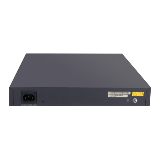
Installation Manual H3C S3100 Series Ethernet Switches Chapter 1 Product Introduction Note: Only the recommended RPS can be used for S3100-26TP-PWR-EI Ethernet switches. The –48 VDC in the equipment room cannot be used directly. Otherwise, the device may be damaged. IV. - Page 26 Installation Manual H3C S3100 Series Ethernet Switches Chapter 1 Product Introduction Note: For details about LEDs on the front panel, refer to section 1.4.1 “Front Panel LEDs of the S3100-SI/S3100-TP-PWR-EI/S3100-C-EPON-EI Series”. II. Rear panel (1) AC power socket (2) Grounding screw Figure 1-28 Rear panel of an S3100-16TP-PWR-EI Ethernet switch III.
-
Page 27: S3100-8Tp-Pwr-Ei
Installation Manual H3C S3100 Series Ethernet Switches Chapter 1 Product Introduction IV. Power system S3100-16TP-PWR-EI Ethernet switches support AC input. Rate voltage range: 100 VAC to 240 VAC, 50 Hz/60 Hz Input voltage range: 90 VAC to 264 VAC, 47 Hz to 63 Hz V. -
Page 28: S3100-26C-Epon-Ei
Installation Manual H3C S3100 Series Ethernet Switches Chapter 1 Product Introduction II. Rear panel (1) AC power socket (2) Grounding screw Figure 1-31 Rear panel of an S3100-8TP-PWR-EI Ethernet switch III. Side panel Each S3100-8TP-PWR-EI Ethernet switch provides a security slot, through which you can lock the device together with an irremovable object to prevent theft. - Page 29 Installation Manual H3C S3100 Series Ethernet Switches Chapter 1 Product Introduction (1): Power Led (PWR) (2): A/L LED (3): D/S LED (4): Port status LED, left (yellow) (5): Port status LED, right (green) (6): 10/100 Base-TX port (7): ONU module (8): Console port (9): LINK LED for the uplink PON port (10): ACT LED for the uplink PON port...
-
Page 30: S3100-16C-Epon-Ei
Installation Manual H3C S3100 Series Ethernet Switches Chapter 1 Product Introduction 1.3.8 S3100-16C-EPON-EI I. Front panel The S3100-16C-EPON-EI provides 16 x 10/100Base-TX Ethernet ports, one 1000 Mbps uplink PON port, and one console port. Figure 1-34 shows the front panel of the S3100-16C-EPON-EI. (1): Power Led (PWR) (2): A/L LED (3): D/S LED... -
Page 31: S3100-8C-Epon-Ei
Installation Manual H3C S3100 Series Ethernet Switches Chapter 1 Product Introduction IV. Cooling system The S3100-16C-EPON-EI cools off naturally. 1.3.9 S3100-8C-EPON-EI I. Front panel The S3100-8C-SI provides 8 x 10/100Base-TX Ethernet ports, one 1000 Mbps uplink PON port, and one console port. Figure 1-36 shows the front panel of the S3100-8C-EPON-EI. -
Page 32: Introduction To Front Panel Leds
Installation Manual H3C S3100 Series Ethernet Switches Chapter 1 Product Introduction Rated voltage range: 100 VAC to 240 VAC, 50 Hz/60 Hz Input voltage range: 90 VAC to 264 VAC, 47 Hz to 63 Hz IV. Cooling system The S3100-8C-EPON-EI cool off naturally. 1.4 Introduction to Front Panel LEDs 1.4.1 Front Panel LEDs of the S3100-SI/S3100-TP-PWR-EI/S3100-C-EPON-EI Series... - Page 33 Installation Manual H3C S3100 Series Ethernet Switches Chapter 1 Product Introduction Table 1-7 Description of port status LEDs on S3100-SI, S3100-TP-PWR-EI, and S3100-C-EPON-EI series Ethernet switches Port status Port status LED Description mode LED The port is in the active state and there Blinking is traffic on the port.
-
Page 34: Front Panel Leds Of The S3100-Tp-Ei Series
Installation Manual H3C S3100 Series Ethernet Switches Chapter 1 Product Introduction 1.4.2 Front Panel LEDs of the S3100-TP-EI Series I. Power LED Table 1-9 Description of the power LED on the S3100-TP-EI series Mark on the panel Status Description The switch is powered on. Power LED Power The switch is powered off. -
Page 35: Technical Specifications
Installation Manual H3C S3100 Series Ethernet Switches Chapter 1 Product Introduction Table 1-12 Description of the Combo port Speed LED of the S3100-TP-EI series Operating port Status Description Connected to a The port is operating 1000 Mbps at 1000 Mbps. optical module 100/1000Base -X SFP port... - Page 36 Installation Manual H3C S3100 Series Ethernet Switches Chapter 1 Product Introduction Item S3100-26T-SI S3100-16T-SI S3100-8T-SI Operating 0°C to 45°C (30°F to 113°F) temperature Relative humidity 10% to 90% (noncondensing) II. S3100-C-SI Table 1-14 Technical specifications for the S3100-C-SI series Item S3100-26C-SI S3100-16C-SI S3100-8C-SI...
- Page 37 Installation Manual H3C S3100 Series Ethernet Switches Chapter 1 Product Introduction Item S3100-26C-SI S3100-16C-SI S3100-8C-SI Both DC-powered switch and AC-powered switch are available to each model. The AC-powered switch supports only AC input, and the DC-powered switch supports only DC input.
-
Page 38: S3100-Ei Series Ethernet Switch
Installation Manual H3C S3100 Series Ethernet Switches Chapter 1 Product Introduction 1.5.2 S3100-EI Series Ethernet Switch I. S3100-TP-EI Table 1-15 Technical specifications for the S3100-TP-EI series Item S3100-26TP-EI S3100-16TP-EI S3100-8TP-EI Physical 43.6 × 440 × 160 43.6 × 360 × 160 43.6 ×... - Page 39 Installation Manual H3C S3100 Series Ethernet Switches Chapter 1 Product Introduction II. S3100-TP-PWR-EI Table 1-16 Technical specifications for the S3100-TP-PWR-EI series S3100-26TP-PW S3100-16TP-PW S3100-8TP-PW Item R-EI R-EI R-EI 43.6 × 440 × 420 43.6 × 300 × 260 43.6 × 300 × 220 Physical dimensions mm (1.7 ×...
- Page 40 Installation Manual H3C S3100 Series Ethernet Switches Chapter 1 Product Introduction Note: S3100-26TP-PWR-EI, S3100-16TP-PWR-EI, and S3100-8TP-PWR-EI Ethernet switches provide an over-temperature protection mechanism. When the internal temperature exceeds 65°C (149°F), they will stop providing power from all ports. When the temperature is below 60°C (140°F), they will continue to provide power from all ports.
-
Page 41: Sfp Modules Supported By S3100-Ei Ethernet Switches
Installation Manual H3C S3100 Series Ethernet Switches Chapter 1 Product Introduction S3100-26C-EPON- S3100-16C-EPON- S3100-8C-EPON-E Item Relative humidity 10% to 90% (non-condensin 1.6 SFP Modules Supported by S3100-EI Ethernet Switches The front panel of S3100-TP-EI and S3100-TP-PWR-EI Ethernet switches provides one or two 1000 Mbps SFP ports in which you can select the required small form-factor pluggable (SFP) modules to insert. - Page 42 Installation Manual H3C S3100 Series Ethernet Switches Chapter 1 Product Introduction Table 1-19 ONU module support of the S3100 series Number of Required or Switch model ONU module model optional modules S3100-8C-SI Optional 1000Base-PX10 (LS6M1PU1SA) S3100-16C-SI Optional 1000Base-PX20 (LS6M1PU1SB) S3100-26C-SI Optional S3100-8C-EPON-EI Required...
- Page 43 Installation Manual H3C S3100 Series Ethernet Switches Chapter 1 Product Introduction Table 1-20 Technical specifications for the ONU port Item Specifications Connector type Number of interfaces Interface speed 1000 Mbps Medium 9/125 µm single-mode fiber 1000Base- PX10: 10 km (6.21 miles) Maximum transmission distance 1000Base- PX20: 20 km (12.43 miles)
-
Page 44: Chapter 2 Installation Preparation
Installation Manual H3C S3100 Series Ethernet Switches Chapter 2 Installation Preparation Chapter 2 Installation Preparation 2.1 Precautions To avoid any device impairment and body injury resulting from improper use, please take the following precautions: Before cleaning the switch, disconnect the power. Do not clean the switch with wet cloth or liquid. -
Page 45: Cleanness Requirements
Installation Manual H3C S3100 Series Ethernet Switches Chapter 2 Installation Preparation rustiness and corrosion of metal parts. If the relative humidity is too low, the captive screws may become loose due to the shrinking of insulation washers; in addition, electrostatic is more likely to be produced in a dry environment, which may damage the circuit of the switch. -
Page 46: Anti-Interference Requirements
Installation Manual H3C S3100 Series Ethernet Switches Chapter 2 Installation Preparation 2.2.3 Anti-interference Requirements A switch in use may be affected by the interference from outside the system by way of capacitance coupling, inductance coupling, electromagnetic radiation, public impedance (including the grounding system) coupling or conducting line (power line, signaling line, and transmission line). - Page 47 Installation Manual H3C S3100 Series Ethernet Switches Chapter 2 Installation Preparation Caution: These installation tools are not shipped with S3100 Series Ethernet Switches. You will have to prepare them beforehand.
-
Page 48: Chapter 3 Installation
Installation Manual H3C S3100 Series Ethernet Switches Chapter 3 Installation Chapter 3 Installation Caution: On a mounting screw of the chassis of the H3C S3100 Series Ethernet Switches, there is a seal labeled with H3C. You must keep it intact before asking the agent to maintain the switch. - Page 49 Installation Manual H3C S3100 Series Ethernet Switches Chapter 3 Installation Table 3-2 Installation method for a switch with a width less than 436 mm (17.2 in.) Use front and Use front Use front Use front Method rear mounting mounting mounting mounting ears and a ears and...
- Page 50 Installation Manual H3C S3100 Series Ethernet Switches Chapter 3 Installation (1) Screw hole used to fix the mounting ear to the cabinet (Use one M6 screw) Figure 3-2 Appearance of a rear mounting ear When you install S3100 Series Ethernet Switches into 19-inch standard cabinets, you should select front mounting ears with a proper length (L1 as shown in Figure 3-1) according to the physical dimensions of switches.
- Page 51 Installation Manual H3C S3100 Series Ethernet Switches Chapter 3 Installation Configuration Configuration Physical dimensions type of front type of rear Model (H × W × D) mounting ear mounting ear S3100-2 43.6 × 440 × 420 mm 6TP-PW Standard Standard (1.7 ×...
- Page 52 Installation Manual H3C S3100 Series Ethernet Switches Chapter 3 Installation Front square-holed bracket Front square-holed bracket Front mounting ear Front mounting ear Front panel Front panel Front Front mounting ear mounting ear Figure 3-4 Fix front mounting ears (2) III. Use front mounting ears and a tray Follow these steps to install a switch into a 19-inch standard cabinet: Wear an ESD-preventive wrist strap to check the grounding and stability of the cabinet.
- Page 53 Installation Manual H3C S3100 Series Ethernet Switches Chapter 3 Installation Three installation locations for screw 1 (select one according to the actual requirement) Three installation locations for screw 1 (select one according to the actual requirement) Screw 1 Screw 1 Screw 1 Screw 1 Front...
- Page 54 Installation Manual H3C S3100 Series Ethernet Switches Chapter 3 Installation Hold the bottom of the switch with one hand and the front part of the switch with the other hand, and push the switch into the cabinet gently, as shown in Figure 3-7.
- Page 55 Installation Manual H3C S3100 Series Ethernet Switches Chapter 3 Installation Fix the other end of the front mounting ears to the front brackets with screws and captive nuts and ensure that front and rear mounting ears have fixed the switch in the cabinet securely, as shown in Figure 3-9.
- Page 56 Installation Manual H3C S3100 Series Ethernet Switches Chapter 3 Installation Note: Guide rails purchased from H3C apply only to standard cabinets 1,000 mm (39.4 in.) deep. Use other supports to substitute for guide rails in the case of other cabinet depths.
- Page 57 Installation Manual H3C S3100 Series Ethernet Switches Chapter 3 Installation Front panel Figure 3-12 Install front mounting ears and guide rails Fix the other end of front mounting ears to the front brackets of the cabinet with M6 screws and captive nuts and ensure that the front mounting ears and guide rails have fixed the switch in the cabinet securely, as shown in Figure 3-13.
-
Page 58: Desk Mounting
Installation Manual H3C S3100 Series Ethernet Switches Chapter 3 Installation Note: No guide rails are delivered with the device. Ensure a clearance of 1U (44.45 mm, namely, 1.75 inches) between devices for the purpose of heat dissipation. 3.1.2 Desk Mounting When a 19-inch standard cabinet is not available, you can simply place the switch on a clean desk. - Page 59 Installation Manual H3C S3100 Series Ethernet Switches Chapter 3 Installation Figure 3-14 Screw (1) Outside edge of anchor kit Figure 3-15 Anchor kit II. Installation procedure The wall-mounting procedure is as follows: As shown in Figure 3-16, drill two holes 5 mm across in the wall on the same horizontal line, with a distance of X mm.
-
Page 60: Magnet Mounting
Installation Manual H3C S3100 Series Ethernet Switches Chapter 3 Installation X mm 1.5 mm(Min) Figure 3-16 Wall mounting Align the two installation holes at the bottom of the switch with these two screws to hang the switch. Caution: When mounting the switch, keep the Ethernet ports of the switch facing downwards and the two sides with ventilation holes vertical to the ground. - Page 61 Installation Manual H3C S3100 Series Ethernet Switches Chapter 3 Installation (1) Permanent magnet (2) M3*6 countersunk head screw Figure 3-17 Magnet and countersunk head screw II. Installation procedure Follow these steps to complete magnet mounting: As shown in Figure 3-18, use a Phillips screwdriver to pass the countersunk head screw through the round hole at the center of the permanent magnet, fasten it to a blind nut in the dent of the switch bottom, and ensure that the permanent magnet and the switch are fastened reliably.
-
Page 62: Installing An Expansion Interface Module
Installation Manual H3C S3100 Series Ethernet Switches Chapter 3 Installation Caution: Apply magnet mounting to only the above two models. Otherwise, a falloff or mis-operation may occur. Select the installation location carefully. In the case of poor surface, magnet mounting may not be reliable. Put the device at a stable place free from vibrations or shocks. -
Page 63: Connection Of Power Cable And Grounding Cable
Installation Manual H3C S3100 Series Ethernet Switches Chapter 3 Installation Step 2: Loosen the fastening screws on both sides of the expansion interface module using a screwdriver. Step 3: Draw back the expansion interface module until the module is fully separated from the switch. - Page 64 Installation Manual H3C S3100 Series Ethernet Switches Chapter 3 Installation both sides of the AC power input, and then set the power cord into the notch of the power cord retainer, as shown in Figure 3-20. (1): Rear panel (2): Power cord retainer holder (3): Power cord retainer (4): Power cord Figure 3-20 Install the power cord retainer...
-
Page 65: Connecting Dc Power Cable
Installation Manual H3C S3100 Series Ethernet Switches Chapter 3 Installation 3.3.2 Connecting DC Power Cable I. DC power cable connection for S3100-C-SI/S3100-TP-EI DC-powered Ethernet switch (1) Screw 1 (2) Screw 2 (3) RTN (+) terminal (4) NEG(-) terminal (–48 V to –60 V) (5) Grounding screw Figure 3-21 DC input terminal block of S3100-C-SI/S3100-TP-EI DC-powered Ethernet switch... - Page 66 Installation Manual H3C S3100 Series Ethernet Switches Chapter 3 Installation Caution: Before powering on the switch, you should properly connect the grounding cable. The DC power cable should be less than 3 meters long. II. DC power cable connection for S3100-26TP-PWR-EI Ethernet switch +...
- Page 67 Installation Manual H3C S3100 Series Ethernet Switches Chapter 3 Installation Use cable ties to bind the two power cables to the protruding part at the back of the air filter, as shown in Figure 3-23. Figure 3-24 Fix the RPS DC power connector to the chassis Insert the connector into the DC socket directly.
-
Page 68: Connecting Grounding Cable
Installation Manual H3C S3100 Series Ethernet Switches Chapter 3 Installation 3.3.3 Connecting Grounding Cable Caution: You should properly connect the switch grounding cable since it is crucial to the lightning protection and electromagnetic shield (EMS) of your switch. The power input end of the switch is connected with a noise filter, whose central ground is directly connected to the chassis, forming the so-called chassis ground (commonly known as PGND). - Page 69 Installation Manual H3C S3100 Series Ethernet Switches Chapter 3 Installation ( 2 ) ( 2 ) ( 2 ) ( 2 ) ( 3 ) ( 3 ) ( 3 ) ( 3 ) ( 1 ) ( 1 ) ( 1 ) ( 1 ) ( 4 )
-
Page 70: Connecting Optical Fiber
Installation Manual H3C S3100 Series Ethernet Switches Chapter 3 Installation ( 1 ) ( 1 ) ( 1 ) ( 1 ) (11 ) (11 ) (11 ) (11 ) ( 2 ) ( 2 ) ( 2 ) ( 2 ) ( 3 ) ( 3 ) ( 3 ) -
Page 71: Connecting Console Cable
Installation Manual H3C S3100 Series Ethernet Switches Chapter 3 Installation Figure 3-29 Console cable Table 3-5 Console cable connector pinouts and mapping relation RJ-45 Signal Direction DB-9 ← ← ← → — → → → 3.5.2 Connecting Console Cable Follow these steps to connect a terminal device, a PC for example, to the switch: Step 1: Connect the DB-9 female connector of the console cable to the serial port of the PC or the terminal device used to configure the switch. -
Page 72: Installation Verification
Installation Manual H3C S3100 Series Ethernet Switches Chapter 3 Installation Note: When connecting a PC to a powered-on switch, you are recommended to connect the DB-9 connector of the console cable to the PC before connecting the RJ-45 connector to the switch. When disconnecting a PC from a powered-on switch, you are recommended to disconnect the DB-9 connector of the console cable from the PC after disconnecting the RJ-45 connector from the switch. -
Page 73: Chapter 4 First Power-On
Installation Manual H3C S3100 Series Ethernet Switches Chapter 4 First Power-on Chapter 4 First Power-on 4.1 Establishing Configuration Environment The following figure shows the configuration environment you will establish: In this environment, a terminal (a PC in this example) is connected to the console port of the switch through the console cable. - Page 74 Installation Manual H3C S3100 Series Ethernet Switches Chapter 4 First Power-on Select [Start/Program/Accessories/Communications/HyperTerminal] to enter the HyperTerminal window, where click the icon to establish a new connection. The system displays the Connection Description interface, as shown in the following figure. Figure 4-2 Connection description interface of HyperTerminal Type in the name of the new connection in the connection description interface and click <OK>.
- Page 75 Installation Manual H3C S3100 Series Ethernet Switches Chapter 4 First Power-on Click <OK> after selecting a serial port and the system pops up the following interface. In the interface, set the bits per second to 9600, data bits to 8, parity check to none, stop bits to 1, and flow control to none.
-
Page 76: Booting Switch
Installation Manual H3C S3100 Series Ethernet Switches Chapter 4 First Power-on Figure 4-6 Set terminal emulation in H3C Properties window 4.4 Booting Switch 4.4.1 Checking Before Powering on the Switch Before powering on the switch, verify that: The power cable and grounding cable are properly connected. The supply voltage is consistent with that required by the switch. - Page 77 Installation Manual H3C S3100 Series Ethernet Switches Chapter 4 First Power-on Copyright(c) 2004-2007 Hangzhou H3C Technologies Co., Ltd. Creation date : Apr 15 2007, 10:12:36 CPU Clock Speed : 200MHz BUS Clock Speed : 33MHz Memory Size : 64MB Mac Address : 000fe20f3100 Press Ctrl-B to enter Boot Menu...
-
Page 78: Changing The Startup Mode
Installation Manual H3C S3100 Series Ethernet Switches Chapter 4 First Power-on ..................................................OK! Starting at 0x80100000... User interface aux0 is available. Press ENTER to get started. 4.4.3 Changing the Startup Mode By default, the system starts up in fast mode. If you want to change the startup mode to normal, press <Ctrl+B>... - Page 79 Installation Manual H3C S3100 Series Ethernet Switches Chapter 4 First Power-on 0. Reboot Enter your choice(0-9): Enter 0, the system reboots in normal mode and displays the following information: Starting..*********************************************************** H3C S3100-16C-SI BOOTROM, Version 506 *********************************************************** Copyright(c) 2004-2007 Hangzhou H3C Technologies Co., Ltd. Creation date : Apr 15 2007, 10:12:36 CPU Clock Speed : 200MHz...
- Page 80 Installation Manual H3C S3100 Series Ethernet Switches Chapter 4 First Power-on PHY selftest.......OK! Please check port leds....FINISHED! User interface aux0 is available. Press ENTER to get started. The appearance of "Press ENTER to get started" indicates that the switch finishes the auto-startup.
-
Page 81: Chapter 5 Boot Rom And Host Software Loading
Installation Manual H3C S3100 Series Ethernet Switches Chapter 5 Boot ROM and Host Software Loading Chapter 5 Boot ROM and Host Software Loading Traditionally, the loading of switch software is accomplished through the serial port. This approach is slow, inconvenient, and cannot be used for remote real-time loading. To resolve these problems, the TFTP and FTP modules are introduced into the switch. -
Page 82: Boot Menu
Installation Manual H3C S3100 Series Ethernet Switches Chapter 5 Boot ROM and Host Software Loading Note: The loading process of the Boot ROM software is the same as that of the host software, except that during the Boot ROM loading process, you should press <Ctrl+U> and <Enter>... -
Page 83: Loading Software Using Xmodem Through Console Port
Installation Manual H3C S3100 Series Ethernet Switches Chapter 5 Boot ROM and Host Software Loading Input the correct Boot ROM password (by default, no password is set on the switch). The system enters the Boot Menu: BOOT MENU 1. Download application file to flash 2. - Page 84 Installation Manual H3C S3100 Series Ethernet Switches Chapter 5 Boot ROM and Host Software Loading 2. Set FTP protocol parameter 3. Set XMODEM protocol parameter 0. Return to boot menu Enter your choice(0-3): Step 2: Enter 3 in the above menu to load the Boot ROM software using XModem. The system displays the following download bits per second setting menu: Please select your download baudrate: 1.* 9600...
- Page 85 Installation Manual H3C S3100 Series Ethernet Switches Chapter 5 Boot ROM and Host Software Loading Figure 5-1 Properties dialog box Figure 5-2 Console port configuration dialog box Step 5: Click the <Disconnect> button to disconnect the HyperTerminal from the switch and then click the <Call> button to reconnect the HyperTerminal to the switch.
- Page 86 Installation Manual H3C S3100 Series Ethernet Switches Chapter 5 Boot ROM and Host Software Loading Figure 5-3 Call and disconnect buttons Note: The new bits per second takes effect only after you disconnect and reconnect the terminal emulation program. Step 6: Press <Enter> to start downloading the program. The system displays the following information: Now please start transfer file with XMODEM protocol.
- Page 87 Installation Manual H3C S3100 Series Ethernet Switches Chapter 5 Boot ROM and Host Software Loading Figure 5-5 Sending file page After the download completes, the system displays the following information: Loading ...CCCCCCCCCC done! Note: You do not need to reset the HyperTerminal’s bits per second and can skip the last step if you have chosen 9600 bps.
-
Page 88: Loading Software Using Tftp Through Ethernet Port
Installation Manual H3C S3100 Series Ethernet Switches Chapter 5 Boot ROM and Host Software Loading The subsequent steps are the same as those for loading the Boot ROM software, except that the system gives the prompt for host software loading instead of Boot ROM loading. -
Page 89: Loading Software Using Ftp Through Ethernet Port
Installation Manual H3C S3100 Series Ethernet Switches Chapter 5 Boot ROM and Host Software Loading 2. Set FTP protocol parameter 3. Set XMODEM protocol parameter 0. Return to boot menu Enter your choice(0-3): Step 4: Enter 1 to download the Boot ROM software using TFTP. Then set the following TFTP-related parameters as required: Load File name :S3100-SI.btm... - Page 90 Installation Manual H3C S3100 Series Ethernet Switches Chapter 5 Boot ROM and Host Software Loading II. Loading Boot ROM software Switch Console port Ethernet port FTP Client FTP Server Figure 5-7 Local loading using FTP Step 1: As shown in Figure 5-7, connect the switch through an Ethernet port to the FTP server, and connect the switch through the console port to the configuration PC.
-
Page 91: Remote Software Loading
Installation Manual H3C S3100 Series Ethernet Switches Chapter 5 Boot ROM and Host Software Loading Step 6: Enter Y to start file downloading or N to return to the BootROM update menu. If you enter Y, the system begins to download and update the program. Upon completion, the system displays the following information: Loading........done Bootrom updating..done! - Page 92 Installation Manual H3C S3100 Series Ethernet Switches Chapter 5 Boot ROM and Host Software Loading 220 WFTPD 2.0 service (by Texas Imperial Software) ready for new user User(none):abc 331 Give me your password, please Password: 230 Logged in successfully [ftp] get s3100-SI.bin [ftp] get s3100-SI.btm [ftp] bye Step 2: Update the Boot ROM program on the switch.
-
Page 93: Remote Loading Using Tftp
Installation Manual H3C S3100 Series Ethernet Switches Chapter 5 Boot ROM and Host Software Loading 5.3.2 Remote Loading Using TFTP The remote loading by using TFTP is similar to the remote loading by using FTP. The only difference is that it is TFTP that you use when loading software to the switch. In this case, the switch can only be used as a TFTP client. -
Page 94: Chapter 6 Maintenance And Troubleshooting
Installation Manual H3C S3100 Series Ethernet Switches Chapter 6 Maintenance and Troubleshooting Chapter 6 Maintenance and Troubleshooting 6.1 Software Loading Failure If software loading fails, the system keeps running in original version. In this case, check if the physical ports are properly connected: If not, reconnect them correctly and restart the loading procedure. -
Page 95: Missing Boot Rom Password
Installation Manual H3C S3100 Series Ethernet Switches Chapter 6 Maintenance and Troubleshooting 7. Skip current configuration file 8. Set bootrom password recovery 9. Set switch startup mode 0. Reboot Enter your choice(0-9): Select <7> and restart the switch. After that, the system will skip the configuration file. 6.2.2 Missing Boot ROM Password Please contact your agent. - Page 96 Installation Manual H3C S3100 Series Ethernet Switches Chapter 6 Maintenance and Troubleshooting Data bits: 8 Parity: None Stop bits: 1 Flow control: None Emulation: VT100.
- Page 97 Installation Manual H3C S3100 Series Ethernet Switches Table of Contents Table of Contents Appendix A Lightning Protection of the Switch.................A-1 A.1 Installation of Lightning Arrester for AC Power (Socket Strip with Lightning Protection)..A-1 A.2 Installation of Lightning Arrester for Network Port.............A-2...
-
Page 98: Appendix A Lightning Protection Of The Switch
Installation Manual H3C S3100 Series Ethernet Switches Appendix A Lightning Protection of the Switch Appendix A Lightning Protection of the Switch A.1 Installation of Lightning Arrester for AC Power (Socket Strip with Lightning Protection) Caution: Lightning arrester will not be shipped with the switch. You should purchase it by yourself if needed. - Page 99 Installation Manual H3C S3100 Series Ethernet Switches Appendix A Lightning Protection of the Switch Caution: Make sure that the arrester is well grounded before using the lightning arrester for power. After inserting AC power cord plug of switch into the socket of lightning arrester, if the green LED is on and the red LED does not alarm, it means that the lightning arrester of power is running and the function of lightning protection has taken effect.
- Page 100 Installation Manual H3C S3100 Series Ethernet Switches Appendix A Lightning Protection of the Switch Multimeter Tilted wire cutter II. Installation procedure Step 1: Tear the protection paper at one side of the double faced adhesive tape apart from the tape, and stick the tape on the surface of the arrester. Tear the protection paper at another side apart from the tape, and stick the arrester onto the chassis of the switch.
- Page 101 Installation Manual H3C S3100 Series Ethernet Switches Appendix A Lightning Protection of the Switch III. Installation precautions Fully consider the following items in the installation process, otherwise, the performance of the lightning arrester for network port will be affected: Lightning arrester for network port is installed in reverse direction. In practice, the “IN”...
Need help?
Do you have a question about the LS-3100-16TP-EI-H3-A-O and is the answer not in the manual?
Questions and answers