H3C S6805 Series Hardware Information
Hide thumbs
Also See for S6805 Series:
- Installation manual (61 pages) ,
- Troubleshooting manual (58 pages) ,
- Configuration manual (38 pages)
Table of Contents
Advertisement
Quick Links
H3C S6805 Switch Series
Hardware Information and Specifications
Document version: 6W100-20220510
Copyright © 2022 New H3C Technologies Co., Ltd. All rights reserved.
No part of this manual may be reproduced or transmitted in any form or by any means without prior written consent of
New H3C Technologies Co., Ltd.
Except for the trademarks of New H3C Technologies Co., Ltd., any trademarks that may be mentioned in this document
are the property of their respective owners.
The information in this document is subject to change without notice
i
Advertisement
Table of Contents

Subscribe to Our Youtube Channel
Related Manuals for H3C S6805 Series


Summary of Contents for H3C S6805 Series
- Page 1 No part of this manual may be reproduced or transmitted in any form or by any means without prior written consent of New H3C Technologies Co., Ltd. Except for the trademarks of New H3C Technologies Co., Ltd., any trademarks that may be mentioned in this document are the property of their respective owners.
-
Page 2: Table Of Contents
Contents 1 Product models and technical specifications ············································ 1-2 Product models ··············································································································································· 1-2 Technical specifications ·································································································································· 1-2 2 Chassis views ·························································································· 2-5 S6805-54HF ···················································································································································· 2-5 S6805-54HT ···················································································································································· 2-6 3 FRUs and compatibility matrixes ······························································ 3-8 Power supplies ················································································································································ 3-8 Fan trays ························································································································································· 3-9 4 Ports and LEDs······················································································... -
Page 3: Product Models And Technical Specifications
Product models and technical specifications Product models The S6805 switch series includes the following models: Product code Product model LS-6805-54HF S6805-54HF LS-6805-54HT S6805-54HT Technical specifications Table1-1 Technical specifications Item S6805-54HF S6805-54HT Dimensions 44 × 440 × 400 mm (1.73 × 17.32 × 15.75 44 ×... - Page 4 Item S6805-54HF S6805-54HT PSR450-12A/PSR450-12A1: • AC input Rated voltage range: 100 to 240 VAC @ 50/60 Hz Max voltage range: 90 to 290 VAC @ 47 to 63 Hz • High-voltage DC input Rated voltage range: 240 VDC ...
- Page 5 Item S6805-54HF S6805-54HT PSR450-12D: • Single DC input: 207 W • Dual DC inputs: 217 W Chassis leakage UL60950-1/EN60950-1/IEC60950-1/GB4943 current compliance PSR250-12A/PSR250-12A1: • 6.3 A @ 250 VAC • 6.3 A @ 250 VDC Melting current of PSR450-12A/PSR450-12A1: • power supply 10 A @ 250 VAC fuse •...
-
Page 6: Chassis Views
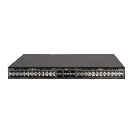
Chassis views S6805-54HF Figure2-1 Front panel (1) SFP+ port (2) SFP+ port LED (3) QSFP28 port (4) QSFP28 port LED Figure2-2 Rear panel (1) Fiber management Ethernet port (2) Console port (3) Mini USB console port (4) USB port (5) Fan tray 1 (6) Fan tray 2 (7) Fan tray 3 (8) Fan tray 4... -
Page 7: S6805-54Ht
Figure2-3 Left side panel (1) Primary grounding point (2) Auxiliary grounding point S6805-54HT Figure2-4 Front panel (1) 1/10GBASE-T autosensing Ethernet port (2) 1/10GBASE-T autosensing Ethernet port LED (3) QSFP28 port (4) QSFP28 port LED Figure2-5 Rear panel (1) Fiber management Ethernet port (2) Console port (3) Mini USB console port (4) USB port... - Page 8 The switch comes with the five fan tray slots empty. You must install five fan trays of the same model for the switch. In Figure2-5, five LSPM1FANSA fan trays are installed in the fan tray slots. Figure2-6 Left side panel (1) Primary grounding point (2) Auxiliary grounding point...
-
Page 9: Frus And Compatibility Matrixes
0231A6NB Fan trays Yes in Release 6616 and later Release versions. For LSPM1FANSA 0231A2VT the support of ESS and Feature versions, contact H3C Support. Yes in Release 6616 and later Release versions. For LSPM1FANSB 0231A2VU the support of ESS and Feature versions, contact H3C Support. -
Page 10: Fan Trays
For more information the power supply side about the power Max input voltage range: 90 to 290 VAC @ 47 to to the port side) supplies, see H3C 63 Hz PSR250-12A & PSR250-12A1 (with Max output power: 250 W ... - Page 11 Specifications Input voltage 12 V Maximum power 9.8 W consumption H3C LSPM1FANSA & LSPM1FANSB Fan Trays User Guide and H3C Documentation reference LSPM1FANSA-SN & LSPM1FANSB-SN Fan Trays User Guide LSPM1FANSB/LSPM1FANSB-SN Dimensions 41 × 40 × 105 mm (1.61 × 1.57 × 4.13 in), including the handle...
-
Page 12: Ports And Leds
• As a best practice, use H3C transceiver modules and cables for the switch. • The H3C transceiver modules and cables are subject to change over time. For the most up-to-date list of H3C transceiver modules and cables, contact H3C Support or marketing staff. -
Page 13: Usb Port
IMPORTANT: • USB devices from different vendors vary in compatibility and driver. H3C does not guarantee correct operation of all USB devices on the switch. If a USB device fails to operate on the switch, replace it with one from another vendor. - Page 14 IMPORTANT: • To use a Gigabit SFP transceiver module except for an SFP-GE-T or SFP-GE-T-D transceiver module to connect an SFP+ port on the switch to the peer end, disable autonegotiation on the peer end. • Installed with an SFP-GE-T or SFP-GE-T-D transceiver module, an SFP+ port can operate only at 1 Gbps.
-
Page 15: Qsfp28 Port
10-Gigabit Central Modal SFP+ Fiber type and waveleng Connector bandwidth transmission transceiver diameter (µm) th (nm) (MHz × km) distance module 66 m (216.54 ft) 33 m (108.27 ft) Multi-mode, 62.5/125 26 m (85.30 ft) SFP-XG-LX-SM1 Single-mode, 1310 10 km (6.21 miles) 9/125 SFP-XG-LH40-S M1550... - Page 16 • QSFP+ fiber cables in Table4-15. • QSFP+ to 4 × 10G SFP+ copper cables in Table4-16. Table4-9 100G QSFP28 transceiver modules available for the QSFP28 ports Central Cable/Fiber Modal Model wavelength Connector type and bandwidth transmission (nm) diameter (µm) (MHz ×...
- Page 17 Model Max transmission distance QSFP-100G-D-CAB-3M 3 m (9.84 ft) QSFP-100G-D-CAB-5M 5 m (16.40 ft) Table4-11 QSFP28 fiber cables available for the QSFP28 ports QSFP28 fiber cable Max transmission distance Data rate QSFP-100G-D-AOC-7M 7 m (22.97 ft) QSFP-100G-D-AOC-10M 10 m (32.81 ft) 100 Gbps QSFP-100G-D-AOC-20M 20 m (65.62 ft)
-
Page 18: 1/10Gbase-T Autosensing Ethernet Port
QSFP+ Central Fiber type Modal transceiver wavelength Connector and diameter bandwidth transmission module (nm) (µm) (MHz × km) distance • 1291 • 1311 • 1331 Four lanes: • 1271 QSFP-40G-LR4 Single-mode, • 1291 2 km (1.24 miles) L-WDM1300 9/125 • 1311 •... -
Page 19: Leds
Table4-17 1/10GBASE-T autosensing Ethernet port specifications Item Specification Connector type RJ-45 Port transmission rate, duplex 1/10 Gbps, full duplex, MDI/MDIX autosensing mode, and auto-MDIX • 55 m (180.45 ft) over category-6 unshielded twisted pair cable Transmission medium and max • 100 m (328.08 ft) over category-6 shielded twisted pair cable transmission distance •... -
Page 20: Qsfp28 Port Led
Table4-19 SFP+ port LED description LED status Description A transceiver module or cable has been correctly installed. The port has a link Steady green and is operating at 10 Gbps. Flashing green The port is sending or receiving data at 10 Gbps. A transceiver module or cable has been correctly installed. -
Page 21: Fan Tray Alarm Leds
Table4-22 Copper management Ethernet port LED description LED mark Status Description Steady green The port is operating at 10/100/1000 Mbps and a link is present. LINK/ACT Flashing green The port is receiving or sending data. No link is present. Table4-23 Fiber management Ethernet port LED description LED mark Status Description... -
Page 22: Cooling System
Cooling system CAUTION: To guarantee heat dissipation, you must install fan trays of the same model for the switch. To dissipate heat timely and ensure system stability, the switch uses the front-rear air aisle cooling system. Consider the site ventilation design when you plan the installation site for the switch. Table5-1 Cooling system for the switch Available fan trays Airflow direction...
Need help?
Do you have a question about the S6805 Series and is the answer not in the manual?
Questions and answers