Sign In
Upload
Download
Table of Contents
Contents
Add to my manuals
Delete from my manuals
Share
URL of this page:
HTML Link:
Bookmark this page
Add
Manual will be automatically added to "My Manuals"
Print this page
×
Bookmark added
×
Added to my manuals
Manuals
Brands
H3C Manuals
Switch
S1600V2 Series
Installation manual
H3C S1600V2 Series Installation Manual
Hide thumbs
Also See for S1600V2 Series
:
Web configuration manual
(60 pages)
1
2
3
4
5
Table Of Contents
6
7
8
9
10
11
12
13
14
15
16
17
18
19
20
21
22
23
page
of
23
Go
/
23
Contents
Table of Contents
Bookmarks
Table of Contents
Table of Contents
Preparing for Installation
Safety Recommendations
Examining the Installation Environment
Cleanliness
Corrosive Gas Limit
Examining the Installation Site
Checking Power Distribution or Power Supply Environment
Installation Tools
Installation Accessories
Installing the Switch
Installation Flowchart
Installing the Device
Installing the Switch in a 19-Inch Rack
Mounting the Switch on a Wall
Mounting the Switch on a Workbench
Grounding the Switch
Grounding the Switch by Using a Grounding Strip
Verifying the Connection after Grounding the Switch
Connecting Power Cords
Check before Power-On
Connecting the AC Power Cord
Connect a Power Adapter
Verifying the Installation
Check after Power-On
Advertisement
Quick Links
Download this manual
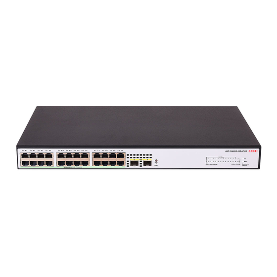
H3C S1600V2 Switch Series
Installation Guide
New H3C Technologies Co., Ltd.
http://www.h3c.com
Document version: 6W100-20240226
Table of
Contents
Previous
Page
Next
Page
1
2
3
4
5
Advertisement
Table of Contents
Need help?
Do you have a question about the S1600V2 Series and is the answer not in the manual?
Ask a question
Questions and answers
Related Manuals for H3C S1600V2 Series
Switch H3C S1600V2 Series Web Configuration Manual
(60 pages)
Switch H3C Mini Series Manual
Unmanaged ethernet switches (18 pages)
Switch H3C S12500 Installation Instructions Manual
Routing switches (126 pages)
Switch H3C S12500 Series Quick Start Manual
(21 pages)
Switch H3C S12500 Series Interface Configuration Manual
Routing switches (23 pages)
Switch H3C S10500 Series Command Reference Manual
(16 pages)
Switch H3C S10500 Series Configuration Manual
(15 pages)
Switch H3C S12500X-AF Series Quick Start Manual
(42 pages)
Switch H3C S1208-PWR Getting Started Manual
(28 pages)
Switch H3C S12500-X Series Configuration Manual
(37 pages)
Switch H3C S12508G-AF Installation Manual
(105 pages)
Switch H3C S12504 Manual
(26 pages)
Switch H3C S10500X-G Series Hardware Information
(87 pages)
Switch H3C S10506X-G Hardware Information
(87 pages)
Switch H3C S10508X-G Hardware Information
(87 pages)
Switch H3C S12500AI Series Installation Manual
(48 pages)
This manual is also suitable for:
Ls-1600v2-6p-gl
S1600v2-6p
Ls-1600v2-10p-gl
S1600v2-10p
Ls-1600v2-18p-gl
S1600v2-18p
...
Show all
Ls-1600v2-26p-gl
S1600v2-26p
Ls-1600v2-6p-hpwr-gl
S1600v2-6p-hpwr
Ls-1600v2-10p-hpwr-gl
S1600v2-10p-hpwr
Ls-1600v2-18p-hpwr-gl
S1600v2-18p-hpwr
Ls-1600v2-26p-hpwr-gl
S1600v2-26p-hpwr
Table of Contents
Print
Rename the bookmark
Delete bookmark?
Delete from my manuals?
Login
Sign In
OR
Sign in with Facebook
Sign in with Google
Upload manual
Upload from disk
Upload from URL


Need help?
Do you have a question about the S1600V2 Series and is the answer not in the manual?
Questions and answers