Keysight PNA Series Selection Manual
Antenna test
Hide thumbs
Also See for PNA Series:
- Quick start manual ,
- Operation and installation manual (100 pages) ,
- Installation and service manual (72 pages)
Table of Contents
Advertisement
Advertisement
Table of Contents

Subscribe to Our Youtube Channel
Related Manuals for Keysight PNA Series


Summary of Contents for Keysight PNA Series
- Page 1 Keysight Technologies Antenna Test Selection Guide...
-
Page 2: Introduction
Keysight. Your Keysight Technologies sales engineer will be glad to assist you in procur- ing the instrumentation. Keysight Technologies does not provide software or integration services for antenna measurement systems. -
Page 3: Table Of Contents
Functional test ......................43 4. Migrating from 8510/8530 to PNA Series ......... 44 Migration from 8510/8530 based antenna systems to PNA Series based systems..44 Engineering services provided for 8510/8530 migration to PNA Series network analyzers ..................45 Migration examples . -
Page 4: Main Parts Of An Antenna Range
Measurement Receiver with LO source (Option 108). Channel Partners Keysight works with channel partners who develop complete antenna test and antenna range solutions. These partners build and install antenna measurement systems work- ing with Keysight engineers to solve customer problems. Keysight instruments such as measurement receivers, network analyzers, sources and accessories, are sold either directly to the end-user or through Keysight channel partners. -
Page 5: Overview Of Antenna Applications Using Keysight Pna Series Network Analyzers
(RCS) test applications. High sensitivity The Keysight PNA-X measurement receiver is a direct replacement for the previous 8530A model with fast throughput and higher measurement sensitivity. The PNA/PNA-X analyzer has a mixer-based architecture providing excellent sensitivity. -
Page 6: Near-Field Antenna Measurements
06 | Keysight | Antenna Test – Selection Guide Pulsed measurements PNA/PNA-X Series Option 021 port-one internal modulator and 025 internal pulse generators add pulsed-RF for pulsed antenna test applications. Combined with Option 008, these gates augment the PNA/PNA-X’s pulse measurement capability by enabling point-in-pulse testing, with pulse widths smaller than 33 ns. -
Page 7: Far-Field Antenna Measurements
07 | Keysight | Antenna Test – Selection Guide Far-field antenna measurements The N5264A PNA-X measurement receiver based system uses 85320A/B broadband external mixers and a 85309B distributed frequency converter and provides the best measurement solution (shown in Figure 4). With Option 108, the internal microwave syn- thesized source can be used as the LO source for the 85309B LO/IF Distribution Unit. - Page 8 08 | Keysight | Antenna Test – Selection Guide Far-field antenna measurements (continued) 85320A Test mixer Source antenna Optional amplifier 85320B Reference PSG Synthesized source mixer PSG or MXG 85309B Positioner PowerSupply LO in 10 MHz LO out (Opt. H11...
- Page 9 09 | Keysight | Antenna Test – Selection Guide Far-field antenna measurements (continued) If the range allows the use of amplifiers instead of a PSG, you can take advantage of the excellent frequency agility of the PNA/PNA-X which minimizes the frequency switching time for far-field measurements configurations.
-
Page 10: Radar Cross-Section Measurements
PNA-L Option 216, PNA Option 201, or PNA-X can also be used. Several additional features of the PNA Series are particularly useful in RCS configurations. – Having the source and receiver integrated into the same instrument, with a choice of frequency ranges is very cost effective in RCS applications. -
Page 11: Banded Millimeter-Wave Measurements
Tx, antenna Rx, antenna T/R module T2 module OML test heads Figure 10. Typical millimeter-wave configuration using a Keysight PNA-X, a mm-wave controller and Oleson Microwave Laboratory mm-wave modules. Legacy (E836xC) PNA analyzer with Option 014, 080, 081, UNL and H11. -
Page 12: Broadband Solution Configuration
12 | Keysight | Antenna Test – Selection Guide Note: Refer to Keysight Technologies Millimeter-Wave Network Analyzers 10 MHz to 110 GHz, with Extensions to 1.1 THz Technical Overview part number 5989-7620EN for the most current information. Broadband Solution Configuration... - Page 13 Add pulse modulator to internal 2nd source Add internal 4 pulse generators Fast CW mode For additional measurement options that are currently only supported up to 67 GHz on the N5227A or N5247A, please refer to the Keysight Network Analyzer Configuration Guide, literature number 5990-7745EN.
- Page 14 14 | Keysight | Antenna Test – Selection Guide Accessories 1.0 mm accessories S-Parameter calibration accessories The following accessories are available for use with the N5250C Please refer to the sidebar for the details of available 1.0 mm test port cables. It is rec- system, but are not included in the ommended for accurate S-parameter measurements at the 1.0 mm port that a 85059A...
- Page 15 15 | Keysight | Antenna Test – Selection Guide Banded Solution Configuration Configuration of a banded solution is similar to configuration of a single sweep solution using separate components. With the support of several frequency extenders and vec- tor network analyzer options, the banded solutions offer industry leading flexibility and extensibility for measurements to 1.1 THz.
- Page 16 Several modules are available and other special options may be configured on request. Select the appropriate quantity of modules required for the measurement set up. To request a specially configured test module contact your local Keysight sales engineer. The single and dual channel receiver modules are used for antenna applications or for 1-port single path S-parametermeasurements.
- Page 17 4 ft cables (LO, IF, Bias) to direct connect mm-head Rec. only to N5222A or N5242A Note When configuring an OML Inc. frequency extender for direct connect please include a 12 V, 1.3 A power supply (e.g. Keysight U8001A). Re- quires one power supply per extender being used for direct connection.
- Page 18 18 | Keysight | Antenna Test – Selection Guide Banded Solution Configuration Millimeter-wave calibration kits (OML Inc.) Waveguide flange Frequency GHz Calibration kit WR15 50 - 75 V11644A WR12 60 - 90 N5260AC12 WR10 75 - 110 W11644A WR08 90 - 140...
- Page 19 19 | Keysight | Antenna Test – Selection Guide Banded Solution Configuration Cable options (Virginia Diodes Inc.) Cable option Description N5262AWCBL-N01 Cables not included for Option 700 or 701 Tx/Rx modules, designed for use with 1.2m cable set. N5262AWCBL-N05 Cables not included for Option 700 or 701 Tx/Rx modules, designed for use with 5m cable set.
- Page 20 20 | Keysight | Antenna Test – Selection Guide Millimeter-wave calibration kits (Virginia Diodes Inc.) Waveguide flange Frequency GHz Calibration kit WR2.2 325 to 500 N5262AC02 WR1.5 500 to 750 N5260AC01 WR1.0 750 to 1.1 THz N5262AC01 Banded waveguide transmission reflection mini-modules (Virginia Diodes Inc.)
-
Page 21: Option Descriptions
– Frequency offset (Option 080) This option enables the PNA Series microwave network analyzers to set the source frequency independently from where the receivers are tuned. 1. These options apply to the E8361C and... - Page 22 – For frequency bands beyond 220 GHz, an improvement of up to 20 dB may be gained for the E836xC PNA Option H11 based configurations. N524xA PNA-X and N522xA PNA Series there is no need to add external sources, please refer to Key- sight Millimiter-Wave Network Analyzers Technical Overview, part number 5989- 7620EN for typical performance.
- Page 23 23 | Keysight | Antenna Test – Selection Guide Figure 12. Typical millimeter-wave antenna application with PNA E836xC with Option 014, 080, 081, UNL and H11. Figure 13. Typical millimeter-wave antenna application with N5242A PNA-X Option 020. For additional information about millimeter measurements, see Application Note 1408-15:...
-
Page 24: Antenna Measurement Design Considerations
24 | Keysight | Antenna Test – Selection Guide 3. Antenna measurement design considerations When designing an antenna measurement system, there are many parameters that must be considered in order to select the optimum equipment. Begin by considering the components for the transmit site, then move to the receive site. Designing a complete... - Page 25 25 | Keysight | Antenna Test – Selection Guide Calculate the effective radiated power The effective radiated power (ERP) is the power level at the output of the transmit an- tenna. – (L ) + G source Where = Effective radiated power (dBm)
- Page 26 26 | Keysight | Antenna Test – Selection Guide Dynamic range The dynamic range required to test the AUT is the difference, in decibels, between maxi- mum boresite level and minimum AUT level that must be measured. Examples of these include side-lobe level, null depth, and cross-polarization levels.
- Page 27 27 | Keysight | Antenna Test – Selection Guide Sensitivity The PNA should be located as closely as possible to the test antenna to minimize the RF cable lengths. The measurement sensitivity of the PNA must be degraded by the inser- tion loss of the RF cable(s) to determine the system measurement sensitivity needed.
- Page 28 The frequency and sensitivity requirements of your antenna system will determine the network analyzer specifications. Keysight offers three families of network analyzers: the PNA Series, the PNA-L Series and the ENA Series. Keysight has developed options for the PNA Series specifically for antenna measurements. Because of these options, the PNA Series is often the preferred analyzer for antenna solutions.
-
Page 29: Receive Site Configuration With External Mixing
29 | Keysight | Antenna Test – Selection Guide Receive site configuration with external mixing RF in 85320A Pin < 26 dBm Test mixer 85320B Pin = 8 to 16 dBm RF in Reference mixer Pin < 26 dBm LO in... - Page 30 A large selection of sources is available for the LO source. In many situations the PNA Series can supply the LO signal since the LO sources only need to operate over the frequency range of 0.3 to 18 GHz.
- Page 31 Series Option H11, the LO frequency must be set so that an 8.33MHz IF is produced. The PNA Series’ LO is offset from its RF by 8.33 MHz automatically if the PNA is operated below 20 GHz and frequency offset is turned off. Refer to “Setting up the PNA LO for an 8.33 MHz IF”, later in this document, for more information.
- Page 32 32 | Keysight | Antenna Test – Selection Guide Power at reference mixer Calculation of the power level at the reference mixer depends on the method used to obtain the reference signal. Almost all ranges obtain the reference channel signal us- ing a stationary reference antenna to receive a portion of the radiated transmit signal.
- Page 33 33 | Keysight | Antenna Test – Selection Guide Power at the analyzer inputs Calculate the IF power levels at the receiver using the following equations: – conversion loss of mixers + conversion gain of 85309B – (L3 + L5) –...
-
Page 34: Determining Measurement Speed
34 | Keysight | Antenna Test – Selection Guide Determining measurement speed Upgrade note: In general, the PNA will provide significant speed improvements over the 8510 or 8530 analyzers. However, some Table 1 shows the measurement speed (for data taking only) of the analyzer. The actual... -
Page 35: Optimizing Speed And Dynamic Range
Optimizing speed and dynamic range Some applications require the fastest speed a system can provide, others are concerned with the best dynamic range available. With the PNA Series network analyzer, users can adjust their setup according to their specific needs. -
Page 36: Legacy Pna Interface Requirements
36 | Keysight | Antenna Test – Selection Guide Legacy PNA interface requirements When configuring the PNA it is critical that power levels are considered to avoid damag- ing the PNA. Ideally, power should not exceed the 0.1 dB compression levels indicated in the figures below. - Page 37 37 | Keysight | Antenna Test – Selection Guide PNA-X N5242A Network Analyzer PORT 1 PORT 2 CPLR ARM RCVR A IN RCVR B IN CPLR ARM +30 dBm +15 dBm +30 dBm +15 dBm SOURCE OUT CPLR THRU CPLR THRU...
- Page 38 38 | Keysight | Antenna Test – Selection Guide Triggering (remote access): - BNC connectors - Edge-triggering (pos/neg) - Trigger in/out - Remote access with SCPI - Available on PNA models E8361C, E836xC, and N5230C. Option H11 Connectors: - PNA RF source and LO outputs for...
- Page 39 39 | Keysight | Antenna Test – Selection Guide Option H11 – IF access Option H11 is only available on the PNA network analyzers. Option H11 also requires Options 014, 080, 081 and UNL. Option H11 provides direct access to the first IF down- conversion stage.
- Page 40 40 | Keysight | Antenna Test – Selection Guide Option H11 – IF access (continued) The 85309 LO/IF distribution unit interfaces with the PNA, PNA-X in two different ways, providing either a 20 MHz IF signal for PNA and PNA-X or an 8.33 MHz for PNA, a 7.606534 MHz for PNA-X and PNA-X measurement receiver IF signal.
- Page 41 41 | Keysight | Antenna Test – Selection Guide Setting up the PNA LO for an 8.33 MHz IF signal Note: The following equations are not required for frequencies under 20 GHz. At The PNA LO must be set so that an 8.33 MHz IF signal is produced by the mixers for...
- Page 42 42 | Keysight | Antenna Test – Selection Guide Using the PNA E836xC front panel Port 1 Source Out as the LO input for the 85309: We know that for a mixer, IF= N(LO) – RF where N = external mixer harmonic number Since IF = 8.33 MHz, then 8.33 = N(LO) –...
-
Page 43: Functional Test
43 | Keysight | Antenna Test – Selection Guide Near-field data collection Frequency multiplexing during a data scan/acquisition can result in a misalignment of the rectangular near-field grid between forward and reverse data scan directions. This introduces an error into the measured near-field data set which results in a far-field pat- tern. -
Page 44: Migrating From 8510/8530 To Pna Series
44 | Keysight | Antenna Test – Selection Guide 4. Migrating from 8510/8530 to PNA Migration from 8510/8530 based antenna systems to PNA network analyzer based systems Table 3 shows the various system components of 8510/8530 based antenna systems and their recommended replacement components. While the components listed are recommended replacements, some interface requirements are different. -
Page 45: Engineering Services Provided For 8510/8530 Migration To Pna Series Network Analyzers
Engineering services provided for 8510/8530 migration to PNA series network analyzers For current users of the 8510/8530 Series of network analyzers, Keysight offers a spec- trum of engineering services that provide training, code conversion, and/or test plan design.These services allow you to take advantage of the excellent performance of the PNA Series with ease. -
Page 46: Migration Examples
46 | Keysight | Antenna Test – Selection Guide Migration examples When migrating from an 8510/8530 to a PNA Series network analyzer, it is important to recog- nize the differences in power, speed and sensitivity between the analyzers. In remote mixing configurations, using Option H11, the damage level of the PNA is much lower than the 8510/8530. - Page 47 47 | Keysight | Antenna Test – Selection Guide Migration examples (continued) 8511A RCS automation software Coupler 83631B Synthesized source Positioner/controller 8530A Personal computer Microwave receiver HP-IB To transmit antenna RF source To computer Figure 29. 85301 RCS system migration to PNA-X N5242A network analyzer.
-
Page 48: Antenna Measurement Components Catalog
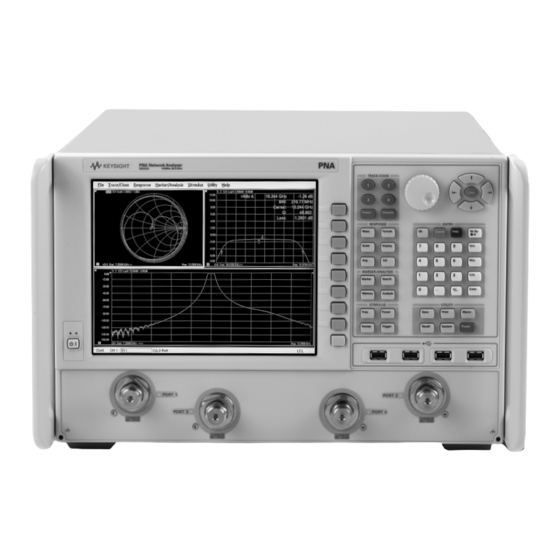
Figure 33. PNA N5222A network analyzer. PNA Series network analyzers The microwave PNA Series instruments are integrated vector network analyzers equipped with a built-in S-parameter test set, synthesized sources, hard and floppy disk drives, and an LCD display. They offer fast data acquisition speeds, excellent sensitivity, wide dynamic range, multiple test channels, and frequency agility –... - Page 49 Frequency offset - Option 080 This option enables the PNA Series microwave network analyzers to set the source frequency independently from where the receivers are tuned. This ability is useful for antenna measurements where the measurement system contains remote mixers and for RCS measurements in pulse mode.
- Page 50 50 | Keysight | Antenna Test – Selection Guide Options (continued) IF inputs for antenna and millimeter-wave - Option 020 - PNA N522xA and PNA-X N524xA The PNA-X IF access option provides network analyzer IF signal path access for applications including antenna measurements, and extended frequency coverage be- yond 26.5 GHz.
- Page 51 The VB application is assigned to one of the PNA’s macro keys for easy access. See Table 1 in section 3 for a list of PNA Series network analyzers, their frequency ranges, power and sensitivity. Refer to the PNA data sheet for additional specifications, literature number 5988-7988EN.
-
Page 52: Sources
When selecting a transmit source for an antenna range, frequency range and output power are the primary concerns. Future frequency requirements should also be con- sidered. Keysight offers a variety of signal generators with different frequency ranges and output power. Source frequency switching speed must also be considered for some applications. - Page 53 53 | Keysight | Antenna Test – Selection Guide Sources (continued) Select a transmit source from the following table: Table 5. Sources High power (Option 1EA) Source Frequency range Output power at Fmax at Fmax (typical) PSG analog signal generators...
-
Page 54: Frequency Converters
54 | Keysight | Antenna Test – Selection Guide Frequency converters Figure 38. 85309 LO/IF distribution unit and 85320A/B mixer modules. The 85309B LO/IF distribution unit and the 85320A/B mixers downconvert a micro- wave signal to an IF signal that can be measured by the PNA. The distributed frequency converter uses external mixers for microwave downconversion. - Page 55 55 | Keysight | Antenna Test – Selection Guide Specifications Table 7. 85309B specifications 85309B Options 40x 85309B Standard or 85309B Options 40x Output Power Limits Options 001 or 002 Output Power Limits for HIGH Band Output Power Limits for LOW Band...
- Page 56 56 | Keysight | Antenna Test – Selection Guide The following diagram shows the power levels for the various mixer configurations. L.O./I.F. Dist. unit 85320A/B Opt H20 85309B Dwn conv. mixers LO out Pin = 6 to 10 dBm chan.
- Page 57 57 | Keysight | Antenna Test – Selection Guide Special options Occasionally an application requires locating the mixers at a distance greater than is possible with a standard 85309B. Greater distances require additional LO output power from the 85309B. Several special options that increase the output power of the 85309B are available.
- Page 58 58 | Keysight | Antenna Test – Selection Guide 85320A/B mixer modules Figure 41. 85320A/B mixer module. The 85320A/B, 85320A/B-H20, and 85320A/B-H50 mixer modules are designed for use with the 85309B LO/IF distribution unit. Each antenna range should have one reference mixer (B model numbers) and one to three text mixers (A model numbers).
- Page 59 59 | Keysight | Antenna Test – Selection Guide 85320A test mixers The 85320A, 85320A-H20 and 85320A-H50 contain a diplexer that combines the LO input and IF output onto a single coaxial connector, which is useful for systems using a rotary joint.
- Page 60 60 | Keysight | Antenna Test – Selection Guide Specifications Frequency range 85320A/B-H20 Fundamental mixing mode 300 MHz to 3 GHz 85320A/B Fundamental mixing mode 1 to 18 GHz 85320A-H50 Fundamental mixing mode 2 to 18 GHz 85320A-H50 Third-harmonic mode...
- Page 61 61 | Keysight | Antenna Test – Selection Guide Specifications (continued) Connector types RF input type-N female (Option H20) 3.5 mm male (standard) 2.4 mm male (Option H50) All other connectors type-N female Environmental characteristics Operating conditions 0 to +55 °C 0 to +45 °C (Option H50)
- Page 62 Figure 45. N5281A frequency converter rear panel detail. Description The Keysight N5280/1A is a four channel frequency converter test set. This test set is used with the Keysight N5242A 2-port or 4-port PNA-X network analyzer, and a N5264A measurement receiver. It can be operated with other microwave accessories (couplers, power splitters).
- Page 63 63 | Keysight | Antenna Test – Selection Guide N5280/1A Test set options: The N5280/1A has two available options: – Standard – There are no attenuators in the RF input paths. – Option 001 – There are four 35 dB attenuators in the RF paths to reduce the power levels.
- Page 64 64 | Keysight | Antenna Test – Selection Guide Figure 47. N5280A block diagram (Standard 700) Figure 48. N5280A block diagram (Option 001)
- Page 65 65 | Keysight | Antenna Test – Selection Guide Figure 49. N5281A block diagram (Standard 700) Figure 50. N5281A block diagram (Option 001)
-
Page 66: Amplifiers
2 to 8 GHz Figure 51. Amplifiers. Keysight Technologies, Inc. has a variety of amplifiers that find applications on antenna and RCS ranges. These amplifiers are small and compact, with high gain and output power. An external power supply is required for these amplifiers. Refer to Keysight’s 83000A Series Microwave System Amplifiers, literature number 5963-5110E, for com- plete information on amplifiers. - Page 67 67 | Keysight | Antenna Test – Selection Guide Table 15. Amplifier specifications Output power Output power Gain Noise Detector Connectors Frequency at P sat at P 1dB (dB) figure output/dc bias (input/out- Model (GHz) (dBm/mW) (dBm/mW) (min) (min) (dB) (typ)
-
Page 68: Multiple-Channel Measurements
68 | Keysight | Antenna Test – Selection Guide Recommended power supplies The 87422A is the recommended power supply for the 83020A amplifier. For all other amplifiers, the recommended power supply is the 87421A. A 2-meter power cable with connectors to connect between amplifier and power supply is provided with all power supplies. - Page 69 69 | Keysight | Antenna Test – Selection Guide Application flexibility Far-field antenna measurements These products are ideally suited for antennas with multiple test ports, or applications that require measuring the co- and cross-polarization response. One PIN switch can switch transmit polarization, and a second PIN switch can switch between the separate test ports of the antenna.
- Page 70 70 | Keysight | Antenna Test – Selection Guide Switch specifications Table 17. 85331/32B specifications Model Frequency ON S21 OFF S21 OFF S22 ON S22 ON S11 Max power number range (db) (db) (db) (db) (db) (dBm) (GHz) 85331B 0.045 to –2.0...
- Page 71 71 | Keysight | Antenna Test – Selection Guide Drive levels Refer to Figure 56 for pin locations. Note the notch and red mark on the bias connector outer ring are used for reference. To turn ON a port, supply a –7VDC (± 0.35V) bias voltage.
-
Page 72: Measurement Automation
Additional COM/DCOM information can be found in Ap- plication Note 1408-13, Keysight literature number 5980-2666EN. Customers can either develop their own software or work with one of Keysight Technolo- gies’ channel partners to develop the code. Keysight channel partners have software... - Page 73 73 | Keysight | Antenna Test – Selection Guide IF input frequencies The IF input frequencies are different depending on the DSP version. With DSP version 4: * RF or Transmitting frequency < 53 MHz: IF = 2.535211 MHz [3 x (60e6 / 71)] * RF or Transmitting frequency >...
-
Page 74: Pna Series Security Features
(The instrument is declassified.) Keysight memory sanitization procedures are designed for customers who need to meet the requirements specified by the US Defense Security Service (DSS). -
Page 75: Pna Series Memory
75 | Keysight | Antenna Test – Selection Guide PNA Series memory This section contains information on the types of memory available in your PNA. It explains the size of memory, how it is used, its location, volatility, and the sanitization procedure. -
Page 76: User And Remote Interface Security Measures
76 | Keysight | Antenna Test – Selection Guide User and remote interface security measures Screen and annotation blanking You can prevent frequency information from appearing on the PNA screen and print- outs. To set security levels from the PNA menu, click System, then Security. When the security level is set to Low or High, frequency information is blanked from the following: –... -
Page 77: Procedure For Declassifying A Faulty Instrument
77 | Keysight | Antenna Test – Selection Guide Procedure for declassifying a faulty instrument When shipped from the factory, all PNAs have PNA-specific files stored on the hard disk drive. When replacing a hard disk drive, in order to achieve specified performance, the PNA-specific files must be copied to the new hard drive. -
Page 78: With Performance Comparable To 8510
78 | Keysight | Antenna Test – Selection Guide Appendix 2: How to select PNA Series (PNA/ PNA-X) IF BW with performance comparable to 8510 Averaging on an 8510 is similar to the IF BW filtering of the PNA, both are like a DSP filter. - Page 79 Figure 57. Configuring an external source. 1. Setting up a source: a) Obtain GPIB addresses of your sources. 2. Setting up PNA Series network analyzers and measurement receivers: a) Select External Source Config…> Utility > System > Configure as shown in the menu below.
- Page 80 80 | Keysight | Antenna Test – Selection Guide The Select Sources dialog box will appear. This shows all sources that were previously added. b) Select Configure if a new source needs to be added. The External Source Configuration dialogue box will appear.
- Page 81 81 | Keysight | Antenna Test – Selection Guide e) From the External Source Configuration dialogue box select the trigger mode. Note: Hardware trigger is TTL and is faster than Software trigger. To learn more, select the Help button. f) From the Select Sources dialogue box: i) Highlight source name.
- Page 82 0800 001122 Keysight Services Belgium 0800 58580 www.keysight.com/find/service Finland 0800 523252 Keysight Services can help from acquisition to renewal across your France 0805 980333 instrument’s lifecycle. Our comprehensive service offerings—one- Germany 0800 6270999 stop calibration, repair, asset management, technology refresh,...
Need help?
Do you have a question about the PNA Series and is the answer not in the manual?
Questions and answers