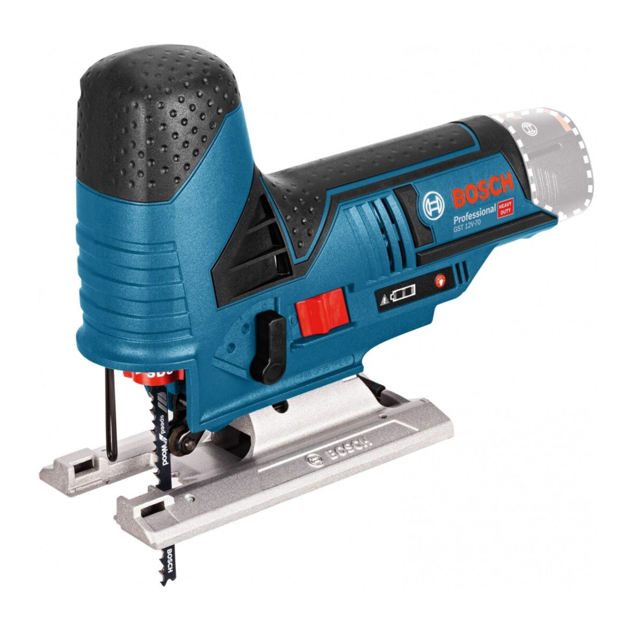
Bosch Professional GST 12V-70 Manual
- Original instructions manual (257 pages) ,
- Original instructions manual (228 pages)
Advertisement
Safety Instructions
General Power Tool Safety Warnings

Read all safety warnings, instructions, illustrations and specifications provided with this power tool. Failure to follow all instructions listed below may result in electric shock, fire and/ or serious injury.
Save all warnings and instructions for future reference. The term "power tool" in the warnings refers to your mainsoperated (corded) power tool or battery-operated (cordless) power tool.
Work area safety
- Keep work area clean and well lit. Cluttered or dark areas invite accidents.
- Do not operate power tools in explosive atmospheres, such as in the presence of flammable liquids, gases or dust. Power tools create sparks which may ignite the dust or fumes.
- Keep children and bystanders away while operating a power tool. Distractions can cause you to lose control.
Electrical safety
- Power tool plugs must match the outlet. Never modify the plug in any way. Do not use any adapter plugs with earthed (grounded) power tools. Unmodified plugs and matching outlets will reduce risk of electric shock.
- Avoid body contact with earthed or grounded surfaces, such as pipes, radiators, ranges and refrigerators. There is an increased risk of electric shock if your body is earthed or grounded.
- Do not expose power tools to rain or wet conditions. Water entering a power tool will increase the risk of electric shock.
- Do not abuse the cord. Never use the cord for carrying, pulling or unplugging the power tool. Keep cord away from heat, oil, sharp edges or moving parts. Damaged or entangled cords increase the risk of electric shock.
- When operating a power tool outdoors, use an extension cord suitable for outdoor use. Use of a cord suitable for outdoor use reduces the risk of electric shock.
- If operating a power tool in a damp location is unavoidable, use a residual current device (RCD) protected supply. Use of an RCD reduces the risk of electric shock.
Personal safety
- Stay alert, watch what you are doing and use common sense when operating a power tool. Do not use a power tool while you are tired or under the influence of drugs, alcohol or medication. A moment of inattention while operating power tools may result in serious personal injury.
- Use personal protective equipment. Always wear eye protection. Protective equipment such as a dust mask, non-skid safety shoes, hard hat or hearing protection used for appropriate conditions will reduce personal injuries.
- Prevent unintentional starting. Ensure the switch is in the off-position before connecting to power source and/or battery pack, picking up or carrying the tool. Carrying power tools with your finger on the switch or energising power tools that have the switch on invites accidents.
- Remove any adjusting key or wrench before turning the power tool on. A wrench or a key left attached to a rotating part of the power tool may result in personal injury.
- Do not overreach. Keep proper footing and balance at all times. This enables better control of the power tool in unexpected situations.
- Dress properly. Do not wear loose clothing or jewellery. Keep your hair and clothing away from moving parts. Loose clothes, jewellery or long hair can be caught in moving parts.
- If devices are provided for the connection of dust extraction and collection facilities, ensure these are connected and properly used. Use of dust collection can reduce dust-related hazards.
- Do not let familiarity gained from frequent use of tools allow you to become complacent and ignore tool safety principles. A careless action can cause severe injury within a fraction of a second.
Power tool use and care
- Do not force the power tool. Use the correct power tool for your application. The correct power tool will do the job better and safer at the rate for which it was designed.
- Do not use the power tool if the switch does not turn it on and off. Any power tool that cannot be controlled with the switch is dangerous and must be repaired.
- Disconnect the plug from the power source and/or remove the battery pack, if detachable, from the power tool before making any adjustments, changing accessories, or storing power tools. Such preventive safety measures reduce the risk of starting the power tool accidentally.
- Store idle power tools out of the reach of children and do not allow persons unfamiliar with the power tool or these instructions to operate the power tool. Power tools are dangerous in the hands of untrained users.
- Maintain power tools and accessories. Check for misalignment or binding of moving parts, breakage of parts and any other condition that may affect the power tool's operation. If damaged, have the power tool repaired before use. Many accidents are caused by poorly maintained power tools.
- Keep cutting tools sharp and clean. Properly maintained cutting tools with sharp cutting edges are less likely to bind and are easier to control.
- Use the power tool, accessories and tool bits etc. in accordance with these instructions, taking into account the working conditions and the work to be performed. Use of the power tool for operations different from those intended could result in a hazardous situation.
- Keep handles and grasping surfaces dry, clean and free from oil and grease. Slippery handles and grasping surfaces do not allow for safe handling and control of the tool in unexpected situations.
Battery tool use and care
- Recharge only with the charger specified by the manufacturer. A charger that is suitable for one type of battery pack may create a risk of fire when used with another battery pack.
- Use power tools only with specifically designated battery packs. Use of any other battery packs may create a risk of injury and fire.
- When battery pack is not in use, keep it away from other metal objects, like paper clips, coins, keys, nails, screws or other small metal objects, that can make a connection from one terminal to another. Shorting the battery terminals together may cause burns or a fire.
- Under abusive conditions, liquid may be ejected from the battery; avoid contact. If contact accidentally occurs, flush with water. If liquid contacts eyes, additionally seek medical help. Liquid ejected from the battery may cause irritation or burns.
- Do not use a battery pack or tool that is damaged or modified. Damaged or modified batteries may exhibit unpredictable behaviour resulting in fire, explosion or risk of injury.
- Do not expose a battery pack or tool to fire or excessive temperature. Exposure to fire or temperature above 130°C may cause explosion.
- Follow all charging instructions and do not charge the battery pack or tool outside the temperature range specified in the instructions. Charging improperly or at temperatures outside the specified range may damage the battery and increase the risk of fire.
Service
- Have your power tool serviced by a qualified repair person using only identical replacement parts. This will ensure that the safety of the power tool is maintained.
- Never service damaged battery packs. Service of battery packs should only be performed by the manufacturer or authorized service providers.
Safety instructions for jigsaws
- Hold the power tool by insulated gripping surfaces, when performing an operation where the cutting accessory may contact hidden wiring. Cutting accessory contacting a "live" wire may make exposed metal parts of the power tool "live" and could give the operator an electric shock.
- Use clamps or another practical way to secure and support the workpiece to a stable platform. Holding the workpiece by hand or against your body leaves it unstable and may lead to loss of control.
- Keep hands away from the sawing area. Do not reach under the workpiece. Contact with the saw blade can lead to injuries.
- Only bring the power tool into contact with the workpiece when switched on. Otherwise there is danger of kickback if the cutting tool jams in the workpiece.
- Ensure that the footplate always rests securely while sawing. A jammed saw blade can break or lead to kickback.
- When the cut is completed, switch off the power tool and then pull the saw blade out of the cut only after it has come to a standstill. In this manner you can avoid kickback and can place down the power tool securely.
- Always wait until the power tool has come to a complete stop before placing it down. The application tool can jam and cause you to lose control of the power tool.
- Use only undamaged saw blades that are in perfect condition. Bent or dull saw blades can break, negatively influence the cut, or lead to kickback.
- Do not brake the saw blade to a stop by applying side pressure after switching off. The saw blade can be damaged, break or cause kickback.
- Only use the power tool with the base plate. If you do not use the base plate, you are at risk of not being able to control the power tool.
- Use suitable detectors to determine if there are hidden supply lines or contact the local utility company for assistance. Contact with electric cables can cause fire and electric shock. Damaging gas lines can lead to explosion. Breaking water pipes causes property damage.
- In case of damage and improper use of the battery, vapours may be emitted. The battery can set alight or explode. Ensure the area is well ventilated and seek medical attention should you experience any adverse effects. The vapours may irritate the respiratory system.
- Do not open the battery. There is a risk of short-circuiting.
- The battery can be damaged by pointed objects such as nails or screwdrivers or by force applied externally. An internal short circuit may occur, causing the battery to burn, smoke, explode or overheat.
- Only use the battery with products from the manufacturer. This is the only way in which you can protect the battery against dangerous overload.
![]()
Protect the battery against heat, e.g. against continuous intense sunlight, fire, dirt, water and moisture. There is a risk of explosion and short-circuiting.
Product Description and Specifications

Read all the safety and general instructions. Failure to observe the safety and general instructions may result in electric shock, fire and/or serious injury.
Please observe the illustrations at the beginning of this operating manual.
Intended Use
The power tool is intended for making separating cuts and cut-outs in wood, plastic, metal, ceramic plates and rubber while resting firmly on the workpiece. It is suitable for straight and curved cuts with mitre/bevel angles of up to 45°. Note the saw blade recommendations.
Product Features

- Batterya)
- Battery release buttona)
- Worklight button
- Battery charge indicator
- Stroke rate preselection thumbwheel
- Temperature monitoring/overload protection indicator
- On/off switch
- Pendulum action adjusting lever
- Base plate
- Guide roller
- Saw blade receptacle
- Guide for parallel guide
- Saw bladea)
- Worklight
- Hood for dust extraction
- Extraction outlet
- Glide shoe
- Anti-splinter guard
- Handle (insulated gripping surface)
- SDS lever for saw blade release
- Shock protection guard
- Extraction hosea)
- Base plate screw
- Hex key
- Scale for mitre/bevel angles
- Locking screw for parallel guidea)
- Parallel guide with circle cuttera)
- Circle cutter centring tipa)
- Accessories shown or described are not included with the product as standard. You can find the complete selection of accessories in our accessories range.
Technical Data
| Cordless jigsaw | GST 12V-70 | |
| Article number | 3 601 EA1 0.. | |
| Rated voltage | V= | 12 |
| No-load stroke rate n₀A) | min−1 | 1500–2800 |
| Stroke | mm | 18 |
| Max. cutting depth | ||
| – in wood | mm | 70 |
| – in aluminium | mm | 3 |
| – in steel (unalloyed) | mm | 3 |
| Max. cutting angle (left/right) | ° | 45 |
| Weight according to EPTA-Procedure 01:2014 | kg | 1.7–1.9B) |
| Recommended ambient temperature during charging | °C | 0 to +35 |
| Permitted ambient temperature during operationC) and during storage | °C | −20 to +50 |
| Recommended rechargeable batteries | GBA 12V... | |
| Recommended chargers | GAL 12... GAX 18... | |
- Measured at 20−25°C with rechargeable batteryGBA 10,8V 2.0Ah.
- Depends on battery in use
- Limited performance at temperatures <0°C
Noise/Vibration Information
Noise emission values determined according to EN 62841‑2‑11.
Typically, the A-weighted sound pressure level of the power tool is 75 dB(A). Uncertainty K = 5 dB. The noise level when working can exceed the volume stated. Wear hearing protection!
Vibration total values ah (triax vector sum) and uncertainty K determined according to EN 62841‑2‑11: Cutting boards with saw blade T 111 C:
ah, B = 4.5 m/s2, K = 1.5 m/s2, cutting sheet metal with saw blade T 118 A:
ah, M = 4.5 m/s2, K = 1.5 m/s2.
The vibration level and noise emission value given in these instructions have been measured in accordance with a standardised measuring procedure and may be used to compare power tools. They may also be used for a preliminary estimation of vibration and noise emissions.
The stated vibration level and noise emission value represent the main applications of the power tool. However, if the power tool is used for other applications, with different application tools or is poorly maintained, the vibration level and noise emission value may differ. This may significantly increase the vibration and noise emissions over the total working period.
To estimate vibration and noise emissions accurately, the times when the tool is switched off or when it is running but not actually being used should also be taken into account. This may significantly reduce vibration and noise emissions over the total working period.
Implement additional safety measures to protect the operator from the effects of vibration, such as servicing the power tool and application tools, keeping their hands warm, and organising workflows correctly.
Assembly
- Remove the battery from the power tool before carrying out work on the power tool (e.g. maintenance, changing tool, etc.). The battery should also be removed for transport and storage. There is risk of injury from unintentionally pressing the on/off switch.
Battery Charging
(see figure A)

- Use only the chargers listed in the technical data. Only these chargers are matched to the lithium-ion battery of your power tool.
 Note: The battery is supplied partially charged. To ensure full battery capacity, fully charge the battery in the charger before using your power tool for the first time.
The lithium-ion battery can be charged at any time without reducing its service life. Interrupting the charging process does not damage the battery.
The lithium-ion battery is protected against deep discharge by the "Electronic Cell Protection (ECP)". When the battery is discharged, the power tool is switched off by means of a protective circuit: The application tool no longer rotates.
- Do not continue to press the On/Off switch after the power tool has automatically switched off. The battery can be damaged.
To remove the battery (1), press the release button (2) and pull the battery downwards out of the power tool. Do not use force to do this.
Battery charge indicator
| LED | Capacity |
| Continuous lighting 1x green | <1/3 |
| Flashing light 1x green | Reserve |
| Flashing light 3x green | Empty |
The three green LEDs of the battery charge indicator (4) indicate the state of charge of the battery (1). The battery charge indicator only lights up for five seconds after startup.
If no LED lights up after switching the power tool on, then the battery is defective and must be replaced.
Inserting/changing the saw blade
- When fitting or changing the saw blade, wear protective gloves. Blades are sharp and can become hot when used for prolonged periods of time.
Selecting the saw blade
You will find an overview of recommended saw blades at the end of these operating instructions. Only use saw blades with single lug shank (T shank). The saw blade should not be longer than required for the intended cut.
Use a narrow saw blade when sawing tight curves.
Inserting the saw blade (see figure B)

- Clean the shaft on the saw blade before inserting it. A dirty shaft cannot be securely fixed in place.
Push the saw blade (13), with the teeth in the cutting direction, into the saw blade receptacle (11) until it clicks into place. The SDS lever (20) automatically springs back and the saw blade is locked in place. Do not push the lever (20) back by hand as you could damage the power tool.
Make sure when inserting the saw blade that the back of the saw blade is in the groove on the guide roller (10).
- Check that the saw blade is seated securely. A loose saw blade can fall out and lead to injuries.
Ejecting the saw blade (see figure C)

- When ejecting the saw blade, hold the power tool in such a manner that no persons or animals can be injured by the ejected saw blade.
Turn the SDS lever (20) as far as it will go in the direction of the shock protection guard (21). The saw blade is released and ejected.
Glide shoe
(see figure D)

When machining sensitive surfaces, you can place the glide shoe (17) on the base plate (9) in order to prevent the surface from being scratched.
To position the glide shoe (17), hook it to the front of the base plate (9), push it up at the back and allow it to click into place.
Anti-splinter guard
(see figure E)

The anti-splinter guard (18) (accessory) can prevent splintering of the surface while sawing wood. The anti-splinter guard can only be used with certain saw blade types and only at a cutting angle of 0°.
Slide the anti-splinter guard (18) into the base plate (9) from the front.
When using the glide shoe (17), the anti-splinter guard (18) is inserted into the glide shoe rather than the base plate (9).
Dust/Chip Extraction
The dust from materials such as lead paint, some types of wood, minerals and metal can be harmful to human health. Touching or breathing in this dust can trigger allergic reactions and/or cause respiratory illnesses in the user or in people in the near vicinity.
Certain dusts, such as oak or beech dust, are classified as carcinogenic, especially in conjunction with wood treatment additives (chromate, wood preservative). Materials containing asbestos may only be machined by specialists.
- Use a dust extraction system that is suitable for the material wherever possible.
- Provide good ventilation at the workplace.
- It is advisable to wear a P2 filter class breathing mask.
The regulations on the material being machined that apply in the country of use must be observed.
- Avoid dust accumulation at the workplace. Dust can easily ignite.
Hood
Fit the hood (15) before you connect the power tool to the dust extraction system.
Attach the hood (15) to the power tool so that the bracket locks into place on the shock protection guard (21).
Remove the hood (15) when working without a dust extraction system and for mitre/bevel cuts. To do this, pull the hood forwards off the shock protection guard (21).
Connecting the dust extraction (see figures F–G)


Fit the extraction outlet (16) in the recesses of the base plate (9).
Connect a dust extraction hose (22) (accessory) to the extraction outlet (16). Connect the dust extraction hose (22) to a dust extractor (accessory).
You will find an overview of connecting to various dust extractors at the end of these operating instructions.
For optimum dust extraction, where possible use the antisplinter guard (18).
The dust extractor must be suitable for the material being worked.
When extracting dry dust that is especially detrimental to health or carcinogenic, use a special dust extractor.
Operation
Operating modes
- Remove the battery from the power tool before carrying out work on the power tool (e.g. maintenance, changing tool, etc.). The battery should also be removed for transport and storage. There is risk of injury from unintentionally pressing the on/off switch.
Pendulum action settings
The pendulum action can be adjusted using three different settings, allowing the cutting speed, cutting capacity and the cut itself to be optimally adapted to the material that you want to cut.
You can also adjust the pendulum action during operation using the adjusting lever (8).
| Level 0 | No pendulum action |
| Level Ⅰ | Low pendulum action |
| Level Ⅱ | High pendulum action |
The optimum pendulum level for each application can be determined by a practical test. Note the following recommendations:
- Select a lower pendulum level or switch off the pendulum action completely if you wish to produce a finer or cleaner cutting edge.
- Switch off the pendulum action when machining thin materials (e.g. sheets).
- Work on hard materials (e.g. steel) with low pendulum action.
- You can work on soft materials and saw wood using maximum pendulum action.
Adjusting the mitre/bevel angle (see figure H)

The base plate (9) can be swivelled to the right or left to make mitre cuts up to 45°.
The extraction outlet (16) and anti-splinter guard (18) cannot be used while mitre/bevel cuts are being made.
- Remove the extraction outlet(16) and the anti-splinter guard (18).
- For mitre/bevel angle 0°, there is a pin in a corresponding recess.
- Loosen the screw(23) with the hex key (24) until you can slide the base plate (9) in towards the battery (1). Let the pin slide into the guide groove.
- To adjust mitre/bevel angles, swivel the base plate(9) to the required position according to the scale (25). Every angle can be adjusted to 45° using a protractor.
- Retighten the screw(23).
Starting Operation
Inserting the battery
Note: The use of batteries unsuitable for your power tool can lead to malfunctions or damage to the power tool.
Insert the charged battery (1) into the battery receptacle until you feel it engage and it is securely locked in place.
Switching on the LED worklight
To switch the worklight (14) on or off, press the worklight button (3).
- Do not look directly into the worklight; it can blind you.
Switching on/off
- Make sure that you are able to press the On/Off switch without releasing the handle.
To switch on the power tool, slide the on/off switch (7) forwards so that "I" appears on the switch. To switch off the power tool, slide the on/off switch (7) backwards so that "0" appears on the switch.
Restart protection
The restart protection feature prevents the power tool from uncontrolled starting after the power supply to it has been interrupted. Once the restart protection is active, the temperature monitoring/overload protection indicator (6) flashes continuously.
To restart the tool, set the on/off switch (7) to the off position and then switch the power tool on again.
Note: Rapidly switching the power tool off and on again may trigger the restart protection, meaning the power tool may not start up even if the on/off switch (7) is pressed. Set the on/off switch (7) to the off position and then switch the power tool on again.
Preselect the stroke rate
You can also preselect the stroke rate and change it during operation using the stroke rate preselection thumbwheel (5).
The required stroke rate is dependent on the material and the work conditions and can be determined using practical tests.
It is recommended that you reduce the stroke rate when placing the saw blade on the workpiece and when sawing plastic and aluminium.
During prolonged periods of use at a low stroke rate, the power tool may heat up significantly. Remove the saw blade and let the power tool run at the maximum stroke rate for around three minutes to cool down.
Temperature-dependent overload protection
In normal conditions of use, the power tool cannot be overloaded. If the power tool is overloaded or not kept within the permitted battery temperature range, the speed is reduced or the power tool switches off. At reduced speed, the power tool will run again at full speed once the permitted battery temperature is reached or the load is reduced. If it automatically shuts down, switch the power tool off, allow the battery to cool down, then switch the power tool back on.
Temperature monitoring/overload protection indicator
The red temperature monitoring/overload protection indicator (6) helps you to protect the battery against overheating and the motor against overload.
If the temperature monitoring/overload protection indicator (6) is lit up permanently in red, the temperature of the battery is too high and the power tool switches off automatically.
Switch the power tool off and allow the battery to cool down before you carry on working.
If the temperature monitoring/overload protection indicator (6) is flashing red, then the power tool is blocked and will switch off automatically.
Pull the power tool out of the workpiece. The power tool will continue to work at the set stroke rate as soon as the blockage is rectified.
Working Advice
- Remove the battery from the power tool before carrying out work on the power tool (e.g. maintenance, changing tool, etc.). The battery should also be removed for transport and storage. There is risk of injury from unintentionally pressing the on/off switch.
- Switch the power tool off immediately if the saw blade becomes blocked.
- Always use a sturdy support when working on small or thin workpieces.
Before sawing into wood, chipboard, building materials, etc., check for and remove any foreign objects such as nails, screws, etc.
Plunge cutting (see figure I)

- Plunge cuts may only be applied to soft materials, such as wood, gypsum board, etc.
For plunge cutting, use only short saw blades. Plunge cutting is possible only with a mitre angle of 0°.
Place the power tool so that the front edge of the base plate (9) rests on the workpiece, without the saw blade (13) touching the workpiece, and switch it on. On power tools with stroke rate control, select the maximum stroke rate. Press the power tool firmly against the workpiece and allow the saw blade to plunge slowly into the workpiece.
As soon as the base plate (9) rests fully on the workpiece, continue sawing along the required cutting line.
Parallel guide with circle cutter (accessory)
When working with the parallel guide with circle cutter (27) (accessory), the workpiece must be no more than 30 mm thick.
Parallel cuts (see figure J):

Loosen the locking screw (26) and slide the scale on the parallel guide through the guide (12) in the base plate. Adjust the desired cutting width as a scale value on the inside edge of the base plate. Retighten the locking screw (26).
Circular cuts (see figure K):

Drill a hole large enough to push the saw blade through on the cutting line within the circle to be cut. Machine the drill hole with a router or file so that the saw blade can lie flush with the cutting line. Position the locking screw (26) on the other side of the parallel guide. Slide the scale on the parallel guide through the guide (12) into the base plate. Drill a hole in the workpiece in the middle of the section to be cut out. Insert the centring tip (28) through the inner opening of the parallel guide and into the drilled hole. Adjust the radius as a scale value on the inside edge of the base plate. Retighten the locking screw (26).
Coolant/lubricant
As the material heats up along the cutting line when cutting metal, you should apply coolant or lubricant.
Recommendations for Optimal Handling of the Battery
Protect the battery against moisture and water.
Only store the battery within a temperature range of −20 to 50°C. Do not leave the battery in your car in the summer, for example.
Occasionally clean the ventilation slots on the battery using a soft brush that is clean and dry.
A significantly reduced operating time after charging indicates that the battery has deteriorated and must be replaced. Follow the instructions on correct disposal.
Maintenance and Service
Maintenance and Cleaning
- Remove the battery from the power tool before carrying out work on the power tool (e.g. maintenance, changing tool, etc.). The battery should also be removed for transport and storage. There is risk of injury from unintentionally pressing the on/off switch.
- To ensure safe and efficient operation, always keep the power tool and the ventilation slots clean.
Clean the saw blade receptacle regularly. For this, remove the saw blade from the power tool and lightly tap out the power tool on a level surface.
If the power tool becomes very dirty, this can lead to serious faults. For this reason, do not cut materials which generate large quantities of dust from below or overhead.
If the dust outlet becomes blocked, switch off the power tool, disconnect the dust extraction system and remove the dust and chips.
Apply a drop of oil to the guide roller (10) from time to time. Check the guide roller (10) regularly. If worn, it must be replaced through an authorised Bosch after-sales service centre.
After-Sales Service and Application Service
Our after-sales service responds to your questions concerning maintenance and repair of your product as well as spare parts. You can find explosion drawings and information on spare parts at: www.bosch-pt.com
The Bosch product use advice team will be happy to help you with any questions about our products and their accessories.
In all correspondence and spare parts orders, please always include the 10‑digit article number given on the nameplate of the product.
Great Britain
Robert Bosch Ltd. (B.S.C.)
P.O. Box 98
Broadwater Park
North Orbital Road
Denham Uxbridge
UB 9 5HJ
At www.bosch-pt.co.uk you can order spare parts or arrange the collection of a product in need of servicing or repair.
Tel. Service: (0344) 7360109
E-Mail: boschservicecentre@bosch.com
You can find further service addresses at: www.bosch-pt.com/serviceaddresses
Transport
The recommended lithium-ion batteries are subject to legislation on the transport of dangerous goods. The user can transport the batteries by road without further requirements.
When shipping by third parties (e.g.: by air transport or forwarding agency), special requirements on packaging and labelling must be observed. For preparation of the item being shipped, consulting an expert for hazardous material is required.
Dispatch battery packs only when the housing is undamaged. Tape or mask off open contacts and pack up the battery in such a manner that it cannot move around in the packaging. Please also observe the possibility of more detailed national regulations.
Documents / Resources
References
Download manual
Here you can download full pdf version of manual, it may contain additional safety instructions, warranty information, FCC rules, etc.
Advertisement


Need help?
Do you have a question about the Professional GST 12V-70 and is the answer not in the manual?
Questions and answers