Bosch Professional GDR 12V-105 Manual
- Original instructions manual (189 pages) ,
- Instructions manual (195 pages)
Advertisement
Product Description and Specifications

Read all the safety and general instructions. Failure to observe the safety and general instructions may result in electric shock, fire and/or serious injury.
Please observe the illustrations at the beginning of this operating manual.
Intended Use
The machine is intended for driving in and loosening screws and bolts as well as for tightening and loosening nuts within the respective range of dimension.
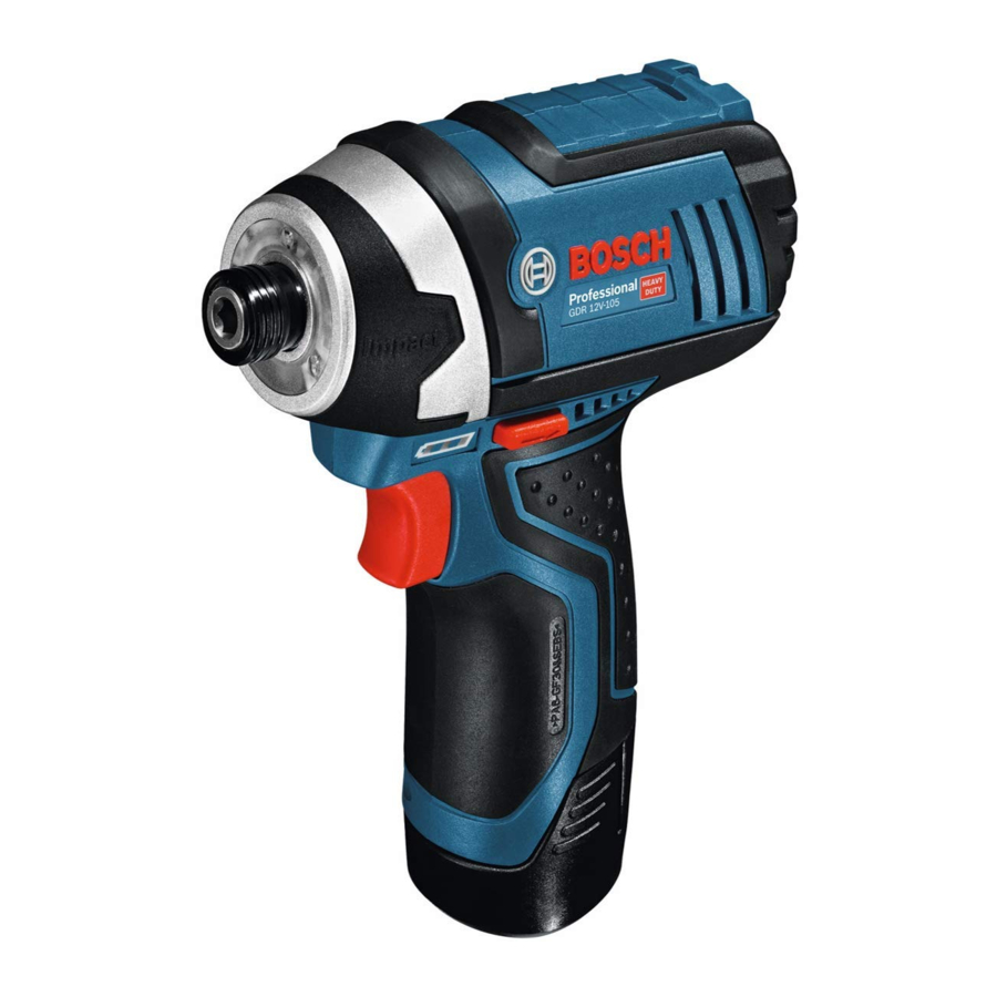
Product Features
The numbering of the product features refers to the diagram of the power tool on the graphics page.

- Tool holder
- Locking sleeve
- Worklight
- Carrying strap lug
- Battery release buttona)
- Rechargeable batterya)
- Rotational direction switch
- On/off switch
- Battery charge indicator
- Handle (insulated gripping surface)
- Universal bit holdera)
- Screwdriver bita)
- Screwdriver bit with ball catcha)
a) This accessory is not part of the standard scope of delivery.
Technical Data
| Cordless Impact Driver | GDR 12V-105 | |
| Article number | 3 601 JA6 9.. | |
| Rated voltage | V= | 12 |
| No-load speed | min -1 | 0–2600 |
| Impact rate | min -1 | 3100 |
| Machine screw diameter | mm | M4–M12 |
| Max. screw diameter | mm | 8 |
| Tool holder | ¼" internal hexagon | |
| WeightA) | kg | 1.0–1.2 |
| Recommended ambient temperature during charging | °C | 0 to +35 |
| Permitted ambient temperature during operationB) and during storage | °C | –20 to +50 |
| Recommended rechargeable batteries | GBA 12V... | |
| Recommended chargers | GAL 12... GAX 18... |
A) Depending on battery in use
B)Limited performance at temperatures < 0°C
Values can vary depending on the product, scope of application and environmental conditions. To find out more, visit www.bosch-professional.com/wac.
Noise/vibration information
Noise emission values determined according to EN 62841-2-2.
Typically, the A-weighted noise level of the power tool is: Sound pressure level 90 dB(A); sound power level 98 dB(A). Uncertainty K = 3 dB.
Wear hearing protection!
Vibration total values ah (triax vector sum) and uncertainty K determined according to EN 62841-2-2:
Tightening screws and nuts of the maximum permitted size:
ah = 9 m/s2, K = 1.5 m/s2
The vibration level and noise emission value given in these instructions have been measured in accordance with a standardised measuring procedure and may be used to compare power tools. They may also be used for a preliminary estimation of vibration and noise emissions.
The stated vibration level and noise emission value represent the main applications of the power tool. However, if the power tool is used for other applications, with different accessories or is poorly maintained, the vibration level and noise emission value may differ. This may significantly increase the vibration and noise emissions over the total working period.
To estimate vibration and noise emissions accurately, the times when the tool is switched off or when it is running but not actually being used should also be taken into account. This may significantly reduce vibration and noise emissions over the total working period.
Implement additional safety measures to protect the operator from the effects of vibration, such as servicing the power tool and accessories, keeping their hands warm, and organising workflows correctly.
Rechargeable battery
Bosch sells some cordless power tools without a rechargeable battery. You can tell whether a rechargeable battery is included with the power tool by looking at the packaging.
Charging the battery
- Use only the chargers listed in the technical data. Only these chargers are matched to the lithium-ion battery of your power tool.
Note: Lithium-ion rechargeable batteries are supplied partially charged according to international transport regulations. To ensure full rechargeable battery capacity, fully charge the rechargeable battery before using your tool for the first time.
Inserting the Battery
Push the charged battery into the battery holder until it clicks into place.
Removing the Battery
To remove the rechargeable battery, press the battery release buttons and pull the battery out. Do not use force to do this.
Battery charge indicator
The battery charge indicator indicates the state of charge for a few seconds when the on/off switch is pressed halfway.
| LED | Capacity |
| 3× continuous green light | 60–100% |
| 2× continuous green light | 30–60% |
| 1× continuous green light | 5–30% |
| 1× flashing green light | 0–5% |
Temperature-dependent overload protection
In normal conditions of use, the power tool cannot be overloaded. If the power tool is overloaded or not kept within the permitted battery temperature range, the speed is reduced or the power tool switches off. At reduced speed, the power tool will run again at full speed once the permitted battery temperature is reached or the load is reduced. If it automatically shuts down, switch the power tool off, allow the battery to cool down, then switch the power tool back on.
Recommendations for Optimal Handling of the Battery
Protect the battery against moisture and water.
Only store the battery within a temperature range of −20 to 50°C. Do not leave the battery in your car in the summer, for example.
A significantly reduced operating time after charging indicates that the battery has deteriorated and must be replaced. Follow the instructions on correct disposal.
Assembly
- Before carrying out any work on the power tool (e.g. maintenance, tool change etc.), remove the battery from the power tool. There is risk of injury from unintentionally pressing the on/off switch.
Changing the tool (see figure A)

- Before carrying out any work on the power tool (e.g. maintenance, tool change etc.), remove the battery from the power tool. There is risk of injury from unintentionally pressing the on/off switch.
Inserting
Pull the locking sleeve (2) forward, guide the application tool (1) into the tool holder up to the stop and release the locking sleeve (2) to lock the application tool.
Use only screwdriver bits with ball catch (13) (DIN 3126E6.3). Other screwdriver bits (12) can be inserted using a universal bit holder with ball catch (11).
Removing the application tool
- Pull the locking sleeve (2) forward and remove the application tool.
Operation
Operating Principle
The tool holder (1) (with the application tool) is driven by an electric motor via a gear and impact mechanism.
The working procedure is divided into two phases:
Screwing in and tightening (impact mechanism in action). The impact mechanism is activated as soon as the screwed connection runs tight and load is therefore put on the motor. The impact mechanism then converts the power of the motor to steady rotary impacts. When loosening screws or nuts, the process is reversed.
Starting Operation
Set the rotational direction (see figure B)
The rotational direction switch (7) is used to change the rotational direction of the power tool. However, this is not possible while the on/off switch (8) is being pressed.
Right rotation: To drive in screws and tighten nuts, press the rotational direction switch (7) through to the left stop. Left Rotation: To loosen and unscrew screws and nuts, press the rotational direction switch (7) through to the right stop.

Switching on/off
To start the power tool, press and hold the on/off switch (8).
The LED (3) lights up when the on/off switch (8) is lightly or fully pressed, meaning that the work area is illuminated in poor lighting conditions.
To switch off the power tool, release the on/off switch (8).
Adjusting the speed
You can adjust the speed of the power tool when it is on by pressing in the on/off switch (8) to varying extents.
A light pressure on the on/off switch (8) results in a low rotational speed. Increased pressure on the switch causes an increase in speed.
Practical advice
The torque depends on the impact duration. The maximum achieved torque results from the sum of all individual torques achieved through impact. Maximum torque is achieved after an impact duration of 6–10 seconds. After this duration, the tightening torque increases only minimally. The impact duration is to be determined for each required tightening torque. The tightening torque actually achieved should always be checked with a torque wrench.
Screw applications with hard, spring-loaded or soft joints
When the achieved torques in an impact series are measured during a test and transferred into a diagram, the result is the curve of a torque characteristic. The height of the curve corresponds with the maximum reachable torque, and the steepness indicates the duration in which this is achieved.
A torque gradient depends on the following factors:
- Strength properties of the screws/nuts
- Type of backing (washer, disc spring, seal)
- Strength properties of the material being screwed/bolted together
- Lubrication conditions at the screw/bolt connection
The following application cases result accordingly:
- Ahard joint is a metal-to-metal screw application which uses washers. After a relatively short impact duration, the maximum torque is reached (steep characteristic curve). Unnecessary long impact duration only causes damage to the machine.
- Aspring-loaded joint is also a metal-to-metal screw application but uses spring washers, disc springs, studs or screws/nuts with conical joints. It is also called a springloaded joint when extensions are used.
- Asoft joint is a screw application of e.g. metal on wood or a screw application that uses lead washers or fibre washers as backing.
For a spring-loaded joint as well as for a soft joint, the maximum tightening torque is lower than for a hard joint. Also, a clearly longer impact duration is required.
Guide values for maximum screw tightening torques
Figures given in Nm; calculated from the tensional cross-section; utilization of the yield point: 90% (with friction coefficient µtotal = 0.12). As a control measure, always check the tightening torque with a torque wrench.
| Property classes according to DIN 267 | Standard screws/bolts | High-strength bolts | |||||||||
| 3.6 | 4.6 | 5.6 | 4.8 | 6.6 | 5.8 | 6.8 | 6.9 | 8.8 | 10.9 | 12.9 | |
| M6 | 2.71 | 3.61 | 4.52 | 4.8 | 5.42 | 6.02 | 7.22 | 8.13 | 9.7 | 13.6 | 16.2 |
| M8 | 6.57 | 8.7 | 11 | 11.6 | 13.1 | 14.6 | 17.5 | 19.7 | 23 | 33 | 39 |
| M10 | 13 | 17.5 | 22 | 23 | 26 | 29 | 35 | 39 | 47 | 65 | 78 |
| M12 | 22.6 | 30 | 37.6 | 40 | 45 | 50 | 60 | 67 | 80 | 113 | 135 |
Tips
Before screwing larger, longer screws into hard materials, it is advisable to pre-drill a pilot hole with the core diameter of the thread to approx. 2/3 of the screw length.
Maintenance and Service
Maintenance and Cleaning
- Before carrying out any work on the power tool (e.g. maintenance, tool change etc.), remove the battery from the power tool. There is risk of injury from unintentionally pressing the on/off switch.
- To ensure safe and efficient operation, always keep the power tool and the ventilation slots clean.
After-Sales Service and Application Service
Our after-sales service responds to your questions concerning maintenance and repair of your product as well as spare parts. You can find explosion drawings and information on spare parts at: www.bosch-pt.com
The Bosch product use advice team will be happy to help you with any questions about our products and their accessories.
In all correspondence and spare parts orders, please always include the 10‑digit article number given on the nameplate of the product.
Great Britain
Robert Bosch Ltd. (B.S.C.)
P.O. Box 98
Broadwater Park
North Orbital Road
Denham Uxbridge
UB 9 5HJ
At www.bosch-pt.co.uk you can order spare parts or arrange the collection of a product in need of servicing or repair.
Tel. Service: (0344) 7360109
E-Mail: boschservicecentre@bosch.com
You can find further service addresses at: www.bosch-pt.com/serviceaddresses
Transport
The recommended lithium-ion batteries are subject to legislation on the transport of dangerous goods. The user can transport the batteries by road without further requirements.
When the batteries are shipped by third parties (e.g. air transport or forwarding agency), special requirements on packaging and labelling (e.g. ADR regulations) must be met. A dangerous goods expert must be consulted when preparing the items for shipping.
Dispatch battery packs only when the housing is undamaged. Tape or mask off open contacts and pack up the battery in such a manner that it cannot move around in the packaging. Please also observe the possibility of more detailed national regulations.
Safety Instructions
General Power Tool Safety Warnings

Read all safety warnings, instructions, illustrations and specifications provided with this power tool. Failure to follow all instructions listed below may result in electric shock, fire and/ or serious injury.
Save all warnings and instructions for future reference. The term "power tool" in the warnings refers to your mainsoperated (corded) power tool or battery-operated (cordless) power tool.
Work area safety
- Keep work area clean and well lit. Cluttered or dark areas invite accidents.
- Do not operate power tools in explosive atmospheres, such as in the presence of flammable liquids, gases or dust. Power tools create sparks which may ignite the dust or fumes.
- Keep children and bystanders away while operating a power tool. Distractions can cause you to lose control.
Electrical safety
- Power tool plugs must match the outlet. Never modify the plug in any way. Do not use any adapter plugs with earthed (grounded) power tools. Unmodified plugs and matching outlets will reduce risk of electric shock. u Avoid body contact with earthed or grounded surfaces, such as pipes, radiators, ranges and refrigerators. There is an increased risk of electric shock if your body is earthed or grounded.
- Do not expose power tools to rain or wet conditions. Water entering a power tool will increase the risk of electric shock.
- Do not abuse the cord. Never use the cord for carrying, pulling or unplugging the power tool. Keep cord away from heat, oil, sharp edges or moving parts. Damaged or entangled cords increase the risk of electric shock.
- When operating a power tool outdoors, use an extension cord suitable for outdoor use. Use of a cord suitable for outdoor use reduces the risk of electric shock. u If operating a power tool in a damp location is unavoidable, use a residual current device (RCD) protected supply. Use of an RCD reduces the risk of electric shock.
Personal safety
- Stay alert, watch what you are doing and use common sense when operating a power tool. Do not use a power tool while you are tired or under the influence of drugs, alcohol or medication. A moment of inattention while operating power tools may result in serious personal injury.
- Use personal protective equipment. Always wear eye protection. Protective equipment such as a dust mask, non-skid safety shoes, hard hat or hearing protection used for appropriate conditions will reduce personal injuries.
- Prevent unintentional starting. Ensure the switch is in the off-position before connecting to power source and/or battery pack, picking up or carrying the tool. Carrying power tools with your finger on the switch or energising power tools that have the switch on invites accidents.
- Remove any adjusting key or wrench before turning the power tool on. A wrench or a key left attached to a rotating part of the power tool may result in personal injury.
- Do not overreach. Keep proper footing and balance at all times. This enables better control of the power tool in unexpected situations.
- Dress properly. Do not wear loose clothing or jewellery. Keep your hair and clothing away from moving parts. Loose clothes, jewellery or long hair can be caught in moving parts.
- If devices are provided for the connection of dust extraction and collection facilities, ensure these are connected and properly used. Use of dust collection can reduce dust-related hazards.
- Do not let familiarity gained from frequent use of tools allow you to become complacent and ignore tool safety principles. A careless action can cause severe injury within a fraction of a second.
Power tool use and care
- Do not force the power tool. Use the correct power tool for your application. The correct power tool will do the job better and safer at the rate for which it was designed.
- Do not use the power tool if the switch does not turn it on and off. Any power tool that cannot be controlled with the switch is dangerous and must be repaired.
- Disconnect the plug from the power source and/or remove the battery pack, if detachable, from the power tool before making any adjustments, changing accessories, or storing power tools. Such preventive safety measures reduce the risk of starting the power tool accidentally.
- Store idle power tools out of the reach of children and do not allow persons unfamiliar with the power tool or these instructions to operate the power tool. Power tools are dangerous in the hands of untrained users.
- Maintain power tools and accessories. Check for misalignment or binding of moving parts, breakage of parts and any other condition that may affect the power tool's operation. If damaged, have the power tool repaired before use. Many accidents are caused by poorly maintained power tools.
- Keep cutting tools sharp and clean. Properly maintained cutting tools with sharp cutting edges are less likely to bind and are easier to control.
- Use the power tool, accessories and tool bits etc. in accordance with these instructions, taking into account the working conditions and the work to be performed. Use of the power tool for operations different from those intended could result in a hazardous situation.
- Keep handles and grasping surfaces dry, clean and free from oil and grease. Slippery handles and grasping surfaces do not allow for safe handling and control of the tool in unexpected situations.
Battery tool use and care
- Recharge only with the charger specified by the manufacturer. A charger that is suitable for one type of battery pack may create a risk of fire when used with another battery pack.
- Use power tools only with specifically designated battery packs. Use of any other battery packs may create a risk of injury and fire.
- When battery pack is not in use, keep it away from other metal objects, like paper clips, coins, keys, nails, screws or other small metal objects, that can make a connection from one terminal to another. Shorting the battery terminals together may cause burns or a fire.
- Under abusive conditions, liquid may be ejected from the battery; avoid contact. If contact accidentally occurs, flush with water. If liquid contacts eyes, additionally seek medical help. Liquid ejected from the battery may cause irritation or burns.
- Do not use a battery pack or tool that is damaged or modified. Damaged or modified batteries may exhibit unpredictable behaviour resulting in fire, explosion or risk of injury.
- Do not expose a battery pack or tool to fire or excessive temperature. Exposure to fire or temperature above 130°C may cause explosion.
- Follow all charging instructions and do not charge the battery pack or tool outside the temperature range specified in the instructions. Charging improperly or at temperatures outside the specified range may damage the battery and increase the risk of fire.
Service
- Have your power tool serviced by a qualified repair person using only identical replacement parts. This will ensure that the safety of the power tool is maintained.
- Never service damaged battery packs. Service of battery packs should only be performed by the manufacturer or authorized service providers.
Safety Warnings for Screwdrivers
- Hold the power tool by insulated gripping surfaces, when performing an operation where the fastener may contact hidden wiring. Fasteners contacting a "live" wire may make exposed metal parts of the power tool "live" and could give the operator an electric shock.
- Use suitable detectors to determine if there are hidden supply lines or contact the local utility company for assistance. Contact with electric cables can cause fire and electric shock. Damaging gas lines can lead to explosion. Breaking water pipes causes property damage.
- Hold the power tool securely. When tightening and loosening screws be prepared for temporarily high torque reactions.
- Secure the workpiece. A workpiece clamped with clamping devices or in a vice is held more secure than by hand.
- Always wait until the power tool has come to a complete stop before placing it down. The application tool can jam and cause you to lose control of the power tool.
- In case of damage and improper use of the battery, vapours may be emitted. The battery can set alight or explode. Ensure the area is well ventilated and seek medical attention should you experience any adverse effects. The vapours may irritate the respiratory system.
- Do not modify or open the battery. There is a risk of short-circuiting.
- The battery can be damaged by pointed objects such as nails or screwdrivers or by force applied externally. An internal short circuit may occur, causing the battery to burn, smoke, explode or overheat.
- Only use the battery in the manufacturer's products. This is the only way in which you can protect the battery against dangerous overload.
![]()
Protect the battery against heat, e.g. against continuous intense sunlight, fire, dirt, water and moisture. There is a risk of explosion and short-circuiting.
Documents / Resources
References
http://www.bosch-professional.com/wac
![www.bosch-pt.com]() Home | Bosch Power Tools
Home | Bosch Power Tools![www.bosch-pt.co.uk]() Home | Bosch Power Tools
Home | Bosch Power ToolsService worldwide
Download manual
Here you can download full pdf version of manual, it may contain additional safety instructions, warranty information, FCC rules, etc.
Advertisement


Need help?
Do you have a question about the Professional GDR 12V-105 and is the answer not in the manual?
Questions and answers