
Bosch PST 700 E / 7000 E / 7200 E Manual
- Original instructions manual (122 pages) ,
- Instructions manual (97 pages) ,
- Original instructions manual (76 pages)
Advertisement
Safety instructions
Electrical safety
![shock hazard]() Power tool plugs must match the outlet. Never modify the plug in any way. Do not use any adapter plugs with earthed (grounded) power tools. Unmodified plugs and matching outlets will reduce risk of electric shock.
Power tool plugs must match the outlet. Never modify the plug in any way. Do not use any adapter plugs with earthed (grounded) power tools. Unmodified plugs and matching outlets will reduce risk of electric shock.![shock hazard]() Avoid body contact with earthed or grounded surfaces, such as pipes, radiators, ranges and refrigerators. There is an increased risk of electric shock if your body is earthed or grounded.
Avoid body contact with earthed or grounded surfaces, such as pipes, radiators, ranges and refrigerators. There is an increased risk of electric shock if your body is earthed or grounded.![shock hazard]() Do not expose power tools to rain or wet conditions. Water entering a power tool will increase the risk of electric shock.
Do not expose power tools to rain or wet conditions. Water entering a power tool will increase the risk of electric shock.![shock hazard]() Do not abuse the cord. Never use the cord for carrying, pulling or unplugging the power tool. Keep cord away from heat, oil, sharp edges or moving parts. Damaged or entangled cords increase the risk of electric shock.
Do not abuse the cord. Never use the cord for carrying, pulling or unplugging the power tool. Keep cord away from heat, oil, sharp edges or moving parts. Damaged or entangled cords increase the risk of electric shock.![shock hazard]() When operating a power tool outdoors, use an extension cord suitable for outdoor use. Use of a cord suitable for outdoor use reduces the risk of electric shock.
When operating a power tool outdoors, use an extension cord suitable for outdoor use. Use of a cord suitable for outdoor use reduces the risk of electric shock.![shock hazard]() If operating a power tool in a damp location is unavoidable, use a residual current device (RCD) protected supply. Use of an RCD reduces the risk of electric shock.
If operating a power tool in a damp location is unavoidable, use a residual current device (RCD) protected supply. Use of an RCD reduces the risk of electric shock.
Personal safety
- Stay alert, watch what you are doing and use common sense when operating a power tool. Do not use a power tool while you are tired or under the influence of drugs, alcohol or medication. A moment of inattention while operating power tools may result in serious personal injury.
- Use personal protective equipment. Always wear eye protection. Protective equipment such as a dust mask, non-skid safety shoes, hard hat or hearing protection used for appropriate conditions will reduce personal injuries.
- Prevent unintentional starting. Ensure the switch is in the off-position before connecting to power source and/or battery pack, picking up or carrying the tool. Carrying power tools with your finger on the switch or energising power tools that have the switch on invites accidents.
- Remove any adjusting key or wrench before turning the power tool on. A wrench or a key left attached to a rotating part of the power tool may result in personal injury.
- Do not overreach. Keep proper footing and balance at all times. This enables better control of the power tool in unexpected situations.
- Dress properly. Do not wear loose clothing or jewellery. Keep your hair and clothing away from moving parts. Loose clothes, jewellery or long hair can be caught in moving parts.
- If devices are provided for the connection of dust extraction and collection facilities, ensure these are connected and properly used. Use of dust collection can reduce dust-related hazards.
- Do not let familiarity gained from frequent use of tools allow you to become complacent and ignore tool safety principles. A careless action can cause severe injury within a fraction of a second.
Power tool use and care
- Do not force the power tool. Use the correct power tool for your application. The correct power tool will do the job better and safer at the rate for which it was designed.
- Do not use the power tool if the switch does not turn it on and off. Any power tool that cannot be controlled with the switch is dangerous and must be repaired.
- Disconnect the plug from the power source and/or remove the battery pack, if detachable, from the power tool before making any adjustments, changing accessories, or storing power tools. Such preventive safety measures reduce the risk of starting the power tool accidentally.
- Store idle power tools out of the reach of children and do not allow persons unfamiliar with the power tool or these instructions to operate the power tool. Power tools are dangerous in the hands of untrained users.
- Maintain power tools and accessories. Check for misalignment or binding of moving parts, breakage of parts and any other condition that may affect the power tool's operation. If damaged, have the power tool repaired before use. Many accidents are caused by poorly maintained power tools.
- Keep cutting tools sharp and clean. Properly maintained cutting tools with sharp cutting edges are less likely to bind and are easier to control.
- Use the power tool, accessories and tool bits etc. in accordance with these instructions, taking into account the working conditions and the work to be performed. Use of the power tool for operations different from those intended could result in a hazardous situation.
- Keep handles and grasping surfaces dry, clean and free from oil and grease. Slippery handles and grasping surfaces do not allow for safe handling and control of the tool in unexpected situations.
Service
- Have your power tool serviced by a qualified repair person using only identical replacement parts. This will ensure that the safety of the power tool is maintained.
Safety instructions for jigsaws
![shock hazard]() Hold the power tool by insulated gripping surfaces, when performing an operation where the cutting accessory may contact hidden wiring or its own cord. Cutting accessory contacting a "live" wire may make exposed metal parts of the power tool "live" and could give the operator an electric shock.
Hold the power tool by insulated gripping surfaces, when performing an operation where the cutting accessory may contact hidden wiring or its own cord. Cutting accessory contacting a "live" wire may make exposed metal parts of the power tool "live" and could give the operator an electric shock.- Use clamps or another practical way to secure and support the workpiece to a stable platform. Holding the workpiece by hand or against your body leaves it unstable and may lead to loss of control.
- Keep hands away from the sawing area. Do not reach under the workpiece. Contact with the saw blade can lead to injuries.
- Only bring the power tool into contact with the workpiece when switched on. Otherwise there is danger of kickback if the cutting tool jams in the workpiece.
- Ensure that the footplate always rests securely while sawing. A jammed saw blade can break or lead to kickback.
- When the cut is completed, switch off the power tool and then pull the saw blade out of the cut only after it has come to a standstill. In this manner you can avoid kickback and can place down the power tool securely.
- Always wait until the power tool has come to a complete stop before placing it down. The application tool can jam and cause you to lose control of the power tool.
- Use only undamaged saw blades that are in perfect condition. Bent or dull saw blades can break, negatively influence the cut, or lead to kickback.
- Do not brake the saw blade to a stop by applying side pressure after switching off. The saw blade can be damaged, break or cause kickback.
- Only use the power tool with the base plate. If you do not use the base plate, you are at risk of not being able to control the power tool.
![burn hazard]()
![shock hazard]()
Use suitable detectors to determine if utility lines are hidden in the work area or call the local utility company for assistance. Contact with electric lines can lead to fire and electric shock. Damaging a gas line can lead to explosion. Penetrating a water line causes property damage or may cause an electric shock.
 Products sold in GB only:
Your product is fitted with an BS 1363/A approved electric plug with internal fuse (ASTA approved to BS 1362).
If the plug is not suitable for your socket outlets, it should be cut off and an appropriate plug fitted in its place by an authorised customer service agent. The replacement plug should have the same fuse rating as the original plug.
The severed plug must be disposed of to avoid a possible shock hazard and should never be inserted into a mains socket elsewhere.
Product Description and Specifications

Read all the safety and general instructions. Failure to observe the safety and general instructions may result in electric shock, fire and/or serious injury.
Please observe the illustrations at the beginning of this operating manual.
Intended Use
The power tool is intended for making separating cuts and cut-outs in wood, plastic, metal, ceramic plates, rubber and laminate/HPL (High Pressure Laminate) while resting firmly on the workpiece. It is suitable for straight and curved cuts with mitre/bevel angles of up to 45°. The saw blade recommendations are to be observed.
Product Features

- On/off switch locking mechanism
- On/off switch
- Dust extraction hosea)
- Dust extraction adaptera)
- Extraction outlet
- Base plate
- Sawdust blower device switch
- Guide roller
- Saw bladea)
- Viewing window for Cut Controla)
- Base for Cut Controla)
- Shock protection guard
- Handle (insulated gripping surface)
- Saw blade receptacle
- Anti-splinter guarda)
- Accessory holder
- Bracket for guide roller
- Base plate screw
- Scale for mitre/bevel angles
- 0° cut marka)
- 45° cut marka)
a) This accessory is not part of the standard scope of delivery.
Technical Data
| Jigsaw | PST 700 E | PST 7000 E | PST 7200 E | |
| Article number | 3 603 CA0 0.. | 3 603 CA0 0.. | 3 603 CA0 0.. | |
| Cut Control | ● | ● | ● | |
| Stroke rate control | ● | ● | ● | |
| Rated power input | W | 500 | 500 | 500 |
| Power output | W | 300 | 300 | 300 |
| No-load stroke rate n0 | min -1 | 500−3100 | 500−3100 | 500−3100 |
| Stroke | mm | 20 | 20 | 20 |
| Max. cutting depth | ||||
| – in wood | mm | 70 | 70 | 72 |
| – in aluminium | mm | 10 | 10 | 10 |
| – in steel (unalloyed) | mm | 4 | 4 | 4 |
| Max. cutting angle (left/right) | ° | 45 | 45 | 45 |
| WeightA) | kg | 1.6 | 1.6 | 1.6 |
| Protection class |  /II /II | /II | /II | |
A) Weight without mains connection cable and without mains plug
The specifications apply to a rated voltage [U] of 230 V. These specifications may vary at different voltages and in country-specific models.
Noise/Vibration Information
Noise emission values determined according to EN 62841‑2‑11.
Typically, the A-weighted noise level of the power tool is:
Sound pressure level 91 dB(A); sound power level 99 dB(A). Uncertainty K = 5 dB.
Wear hearing protection!
Vibration total values ah (triax vector sum) and uncertainty K determined according to EN 62841‑2‑11:
Cutting boards with saw blade T 144 D:
ah, B = 10 m/s2, K = 3 m/s2,
cutting sheet metal with saw blade T 118 A:
ah, M = 11 m/s2, K = 3 m/s2.
The vibration level and noise emission value given in these instructions have been measured in accordance with a standardised measuring procedure and may be used to compare power tools. They may also be used for a preliminary estimation of vibration and noise emissions.
The stated vibration level and noise emission value represent the main applications of the power tool. However, if the power tool is used for other applications, with different accessories or is poorly maintained, the vibration level and noise emission value may differ. This may significantly increase the vibration and noise emissions over the total working period.
To estimate vibration and noise emissions accurately, the times when the tool is switched off or when it is running but not actually being used should also be taken into account. This may significantly reduce vibration and noise emissions over the total working period.
Implement additional safety measures to protect the operator from the effects of vibration, such as servicing the power tool and accessories, keeping their hands warm, and organising workflows correctly.
Assembly
- Pull the plug out of the socket before carrying out any work on the power tool.
Inserting/changing the blade
- When fitting or changing the saw blade, wear protective gloves. Blades are sharp and can become hot when used for prolonged periods of time.
Selecting the blade
You will find an overview of recommended saw blades at the end of these operating instructions. Only use saw blades with a single lug shank (T shank) or with a 1/4" universal shank (U shank). The saw blade should not be longer than required for the intended cut.
Use a narrow saw blade when sawing tight curves.
Inserting the blade
- Clean the shaft on the saw blade before inserting it. A dirty shaft cannot be securely fixed in place.
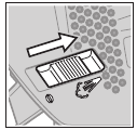
(see figures A and E)
Push the saw blade receptacle (14) upwards in the direction of the arrow. Push the saw blade (9), with the teeth in the cutting direction, into the saw blade receptacle as far as it will go.
Make sure when inserting the saw blade that the back of the saw blade is in the groove on the guide roller (8).
Precise cuts are only possible if the guide roller (8) fits closely – but not too tightly – against the back of the saw blade (ensure that the saw blade (9) is not bent by the guide roller). If necessary, loosen the screw (18) and slide the bracket (17) for the guide roller so that the guide roller fits closely against the back of the saw blade. Retighten the screw (18).


- Check that the saw blade is seated securely. A loose saw blade can fall out and lead to injuries.
Removing the blade

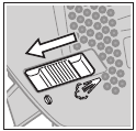
(see figure B)
Push the saw blade receptacle (14) upwards in the direction of the arrow and remove the saw blade (9).
If the saw blade jams during removal, press the saw blade receptacle (14) slightly forward (max. 2 mm).
Anti-splinter guard

(see figure C)
The anti-splinter guard (15) can prevent splintering of the surface while sawing wood. The anti-splinter guard can only be used with certain saw blade types and only at a cutting angle of 0°. When sawing with the anti-splinter guard, the base plate (6) must not be moved to the rear for sawing close to edges.
Push the anti-splinter guard (15) into the base plate (6) from below (as shown in the figure with the groove facing upwards).
Cut Control
Cut Control enables the power tool to be guided precisely along a cutting line marked on the workpiece. Cut Control includes the viewing window (10) with cut marks and the base (11) for securing to the power tool.

Securing Cut Control to the base plate (see figure D)
Firmly insert the viewing window for Cut Control (10) into the brackets on the base (11). Then push the base together gently and allow it to click into place in the accessory holder (16) on the base plate (6).
Dust/Chip Extraction
The dust from materials such as lead paint, some types of wood, minerals and metal can be harmful to human health. Touching or breathing in this dust can trigger allergic reactions and/or cause respiratory illnesses in the user or in people in the near vicinity.
Certain dusts, such as oak or beech dust, are classified as carcinogenic, especially in conjunction with wood treatment additives (chromate, wood preservative). Materials containing asbestos may only be machined by specialists.
- Use a dust extraction system that is suitable for the material wherever possible.
- Provide good ventilation at the workplace.
- It is advisable to wear a P2 filter class breathing mask.
The regulations on the material being machined that apply in the country of use must be observed.
- Avoid dust accumulation at the workplace. Dust can easily ignite.
Connecting the dust extraction system
Insert the dust extraction adapter (4) into an extraction hose (3) until you hear it click into place. Connect the dust extraction adapter (4) to the extraction outlet (5) on the power tool and the extraction hose (3) to a dust extractor (accessory).
You will find an overview of connecting to various dust extractors at the end of these operating instructions.
For optimum dust extraction, where possible use the antisplinter guard (15).
Switch off the sawdust blower device when you have connected the dust extraction system.
The dust extractor must be suitable for the material being worked.
When extracting dry dust that is especially detrimental to health or carcinogenic, use a special dust extractor.
Operation
- Products that are only sold in AUS and NZ: Use a residual current device (RCD) with a nominal residual current of 30 mA or less.
Operating modes
- Pull the plug out of the socket before carrying out any work on the power tool.
Adjusting the mitre angle
(see figures E–F)
The base plate (6) can be swivelled to the right or left to make mitre cuts up to 45°.
The anti-splinter guard (15) cannot be used while mitre cuts are being made.

- Insert a saw blade (9).
- Remove the anti-splinter guard (15).
- Loosen the screw (18) and push the base plate (6) slightly towards the extraction outlet (5).
- The base plate has lock-in points at 0°, 22.5° and 45° on the left and right so that the precise mitre angle can be adjusted. Swivel the base plate (6) to the desired position according to the scale (19). Other mitre angles can be adjusted using a protractor.
- Then push the base plate (6) towards the saw blade (9) as far as it will go.
- Slide the bracket (17) so that the guide roller (8) fits against the back of the saw blade. Precise cuts are only possible when the guide roller fits closely against the back of the saw blade.
- Retighten the screw (18).
Cut Control for mitre cuts

To enable you to track the cutting line (Cut Control), the viewing window for Cut Control (10) has a mark (20) for right-angled cuts at 0° and a mark (21) for rightward- and leftward-slanting mitre cuts at 45° according to the scale (19).
The cut mark for mitre angles between 0° and 45° is proportional. It can also be marked on the viewing window for Cut Control (10) using a non-permanent marker and easily removed again.
We recommend making a test cut for precise results.
Moving the base plate
(see figure E)
You can move the base plate (6) back for sawing close to edges.
Insert a saw blade (9).
Loosen the screw (18) and push the base plate (6) towards the extraction outlet (5) as far as it will go.
Slide the bracket (17) so that the guide roller (8) fits against the back of the saw blade. Precise cuts are only possible when the guide roller fits closely against the back of the saw blade.
Retighten the screw (18).
Sawing with an offset base plate (6) is only possible with a mitre angle of 0°. In addition, Cut Control must not be used with the base (11) or the anti-splinter guard (15).
Sawdust blower device
The cutting line can be kept clear of chips using the airflow from the sawdust blower device.
To switch on the sawdust blower device: When working with high material removal in wood, plastic and other similar materials, push the switch (7) towards the extraction outlet.
To switch off the sawdust blower device: When working in metal and with a dust extraction system connected, push the switch (7) towards the saw blade.
Starting Operation
- Pay attention to the mains voltage. The voltage of the power source must match the voltage specified on the rating plate of the power tool.
Switching on/off
- Make sure that you are able to press the On/Off switch without releasing the handle.
To switch on the power tool, press the on/off switch (2).
To lock the on/off switch (2), keep it pressed down and push the locking mechanism (1) to the right or left.
To switch off the power tool, release the on/off switch (2). If the on/off switch (2) is locked, press the switch first and then release it.
Controlling the stroke rate
You can variably adjust the stroke rate of the power tool when it is on by pressing in the on/off switch (2) to varying extents.
Applying light pressure to the on/off switch (2) results in a low stroke rate. Applying increasing pressure to the switch increases the stroke rate.
The required stroke rate depends on the material and the working conditions and can be ascertained through practical tests.
A reduction in the stroke rate is recommended:
- When positioning the saw blade on the workpiece in order to be able to position the saw blade more precisely,
- When sawing plastic and aluminium to prevent the material from melting.
During prolonged periods of use at a low stroke rate, the power tool may heat up significantly. Remove the saw blade and let the power tool run at the maximum stroke rate for around three minutes to cool down.
Working Advice
- Pull the plug out of the socket before carrying out any work on the power tool.
- Switch the power tool off immediately if the saw blade becomes blocked.
- When machining small or thin workpieces, always use a stable base or saw table (accessory).
Saw with moderate pressure in order to achieve optimal and precise cutting results.
Jigsaws are primarily designed for curved cuts. The range of products from Bosch also includes accessories which enable straight cuts or circular cuts (depending on the jigsaw model, e.g. parallel guide, guide rail or circle cutter).
Hand-held jigsaws generally tend to go off at an angle, i.e. under certain circumstances the angle and cutting accuracy can no longer be ensured. Decisive influencing factors on the accuracy are the saw blade thickness, cutting length and the material thickness and strength of the workpiece.
When making long, straight cuts in thick wood (>40 mm), the cutting line may not be entirely precise. In this case, for precise cuts, it is recommended that you use a Bosch circular saw.
Therefore, always check using test cuts whether the cutting result of the selected system meets the requirements of your application.
Plunge cutting
- Plunge cuts may only be applied to soft materials, such as wood, gypsum board, etc.

(see figure G)
For plunge cutting, use only short saw blades. Plunge cutting is possible only with a mitre angle of 0°.
Place the power tool so that the front edge of the base plate (6) rests on the workpiece, without the saw blade (9) touching the workpiece, and switch it on. On power tools with stroke rate control, select the maximum stroke rate. Press the power tool firmly against the workpiece and allow the saw blade to plunge slowly into the workpiece.
As soon as the base plate (6) rests fully on the workpiece, continue sawing along the required cutting line.
Coolant/lubricant
As the material heats up along the cutting line when cutting metal, you should apply coolant or lubricant.
Maintenance and Service
Maintenance and Cleaning
- Pull the plug out of the socket before carrying out any work on the power tool.
- To ensure safe and efficient operation, always keep the power tool and the ventilation slots clean.
In order to avoid safety hazards, if the power supply cord needs to be replaced, this must be done by Bosch or by an after-sales service centre that is authorised to repair Bosch power tools.
Clean the saw blade receptacle regularly. For this, remove the saw blade from the power tool and lightly tap out the power tool on a level surface.
If the power tool becomes very dirty, this can lead to serious faults. For this reason, do not cut materials which generate large quantities of dust from below or overhead.
- In extreme conditions, always use a dust extractor if possible. Blow out ventilation slots frequently and install a residual current device (RCD) upstream. When machining metals, conductive dust can settle inside the power tool, which can affect its protective insulation.
If the dust outlet becomes blocked, switch off the power tool, disconnect the dust extraction system and remove the dust and chips.
Apply a drop of oil to the guide roller (8) from time to time.
Check the guide roller (8) regularly. If worn, it must be replaced through an authorised Bosch after-sales service centre.
After-Sales Service and Application Service
Our after-sales service responds to your questions concerning maintenance and repair of your product as well as spare parts. You can find explosion drawings and information on spare parts at: www.bosch-pt.com
The Bosch product use advice team will be happy to help you with any questions about our products and their accessories.
In all correspondence and spare parts orders, please always include the 10‑digit article number given on the nameplate of the product.
Great Britain
Robert Bosch Ltd. (B.S.C.)
P.O. Box 98
Broadwater Park
North Orbital Road
Denham Uxbridge
UB 9 5HJ
At www.bosch-pt.co.uk you can order spare parts or arrange the collection of a product in need of servicing or repair.
Tel. Service: (0344) 7360109
E-Mail: boschservicecentre@bosch.com
You can find further service addresses at:
www.bosch-pt.com/serviceaddresses
Documents / Resources
References
Download manual
Here you can download full pdf version of manual, it may contain additional safety instructions, warranty information, FCC rules, etc.
Advertisement


Need help?
Do you have a question about the PST 700 E and is the answer not in the manual?
Questions and answers